W&C SL20K Скачать руководство пользователя страница 8


SL20K Self-Steering Axle and Suspension System Installation Manual


9.  Mark  the  location  of  the  mounting  holes  on 

the outside of both suspension frame rails. 
 

10.  Inspect  vehicle  frame  rails  for  any  items  that 

may cause drilling obstructions. 


Welding,  drilling  or  bolting  through  the  bottom 
flange  of  the  suspension  frame  or  vehicle  rails 
voids the manufacturer’s warranty. 


NOTE 

3/4”  SAE  Grade  8  UNF  fasteners  required  to 
attach  the  SL2065  suspension  to  the  vehicle 
frame. 


11.  Drill 

two 

13/16” 

holes 

through 

each 

suspension rail and vehicle frame rail.


12.  Fasten  each  suspension  side  rail  to  the 

vehicle 

frame 

using 

the 

appropriate 

size/grade  fastener  specified  above,  flat 
washer and lock nut. Use at least 2 bolts per 
side.


13.  Drill  remaining  mounting  holes  per  side  rail. 

See  Figure  7  or  the  supplied  suspension 
drawing for recommended fastener quantities 
and locations. 
 

14.  Install  the  remaining  bolts,  washers and  lock 

nuts and tighten cap screws to proper torque. 
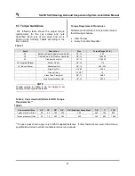
See  “Torque  Requirements”  on  page  13


for 

details. 


15.  Drill a minimum of two 13/16” diameter holes 

through  the  upper  air  spring  mounting 
brackets and chassis frame. 


16.  Fasten each bag plate assembly with two ¾” 

SAE  grade  8  UNF  fine  thread  cap  screws, 
flat  washers  and  lock  nuts  as  seen  in  figure 
7.  


NOTE 

Hangers  must  be  parallel  to  one  another  to 
ensure proper operation. 


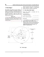
FIG – 6 Frame Alignment 

Содержание SL20K

Страница 1: ...________ 3 4 Installation _____________________________4 4 1 Mounting the Suspension_____________ 4 4 2 Adjusting Maximum Turn Angle ________ 8 4 3 Adjusting Wheel Toe in ______________ 9 5 Torque Req...

Страница 2: ...ensions upon delivery The vehicle manufacturer must approve any changes to the vehicle frame before the changes are done Cutting or altering the vehicle s frame is normally not permitted by the manufa...

Страница 3: ...the manufacturer s warranty 2 2 Warning Proper axle attachment required for safe operation of the vehicle No alteration of any Watson Chalin suspension components is permitted without proper authoriz...

Страница 4: ...ied on the corresponding drawing when the vehicle is in its loaded condition Watson Chalin provides numerous different SL series suspension systems to accommodate different vehicle ride heights and ca...

Страница 5: ...not carry its share of the load straining the other suspension components When there is too little ground clearance or if the suspension is overloaded the vehicle will bottom out while going over bum...

Страница 6: ...Axle and Suspension System Installation Manual 5 NOTE Throughout the installation process you must check frequently for suspension clearance problems while mounting the suspension FIG 4 Chassis Crossm...

Страница 7: ...riving the rear axles and tires onto a lift 7 Raise the suspension into position using the marked axle front hanger rail and upper bag plate center line as locators NOTE If while raising the SL series...

Страница 8: ...n side rail to the vehicle frame using the appropriate size grade fastener specified above flat washer and lock nut Use at least 2 bolts per side 13 Drill remaining mounting holes per side rail See Fi...

Страница 9: ...1 Measure the current Turn Angle 2 The maximum turn angle for SL2065 Series model is normally set at the maximum 25 Some applications may require less turn angle 3 If the turn angle needs to be adjust...

Страница 10: ...tires around the complete outer surface of the tire 4 Place the pointers of a trammel bar on the marks of each tire and rotate the tires making sure a straight line has been marked 5 Measure and reco...

Страница 11: ...llowing tables are applied to nuts but not bolts All torque requirements are for lubricated threads only A lubricated thread is defined as a bolted connection that has some form of friction modifier o...

Страница 12: ...rements Torque values shown apply only to W C supplied fasteners If other fasteners are used follow torque specifications listed in vehicle manufacturer s service manual Item Description Size Torque R...

Страница 13: ...proper torque as specified below U Bolt Non Plated Clean Lubricated Thread Torque Requirements Airspring Torque Requirements Airspring Air Fitting Torque Requirements UNF Grade 8 Size 3 8 1 2 5 8 3 4...

Страница 14: ...69 74 78 83 11 5 20 30 40 49 59 68 73 78 83 88 SL2065 12 10 18 27 35 44 52 61 65 70 74 78 11 25 19 28 37 46 55 65 69 74 78 83 12 5 20 30 40 49 59 68 73 78 83 88 SL2065 13 11 18 27 35 44 52 61 65 70 7...

Страница 15: ...14 7 Parts List The following section shows the exploded view of the SL2065 series lift axle This view and corresponding parts list in the following table is intended to help you identify parts and pa...

Страница 16: ...LIFT BAG HARDWARE PACK 18 1 CHART 4 LIFT BAG PLUMBING KIT HARDWARE 19 1 CHART 2 SL2055 COMMON PVT HDWE 20 1 HPPT16094 PIVOT CONNECTION PACK 21 1 011707 1 BACKBONE LH 20K INT BRAKE 012137 1 BACKBONE L...

Страница 17: ...AKE 33 2 REF ONLY HUB ASSEMBLY 34 2 REF ONLY BRAKE DRUM 35 2 REF ONLY SEAL 36 2 REF ONLY INNER BEARING 37 2 REF ONLY OUTER BEARING 38 2 REF ONLY SPINDLE NUT 39 2 REF ONLY HUB CAP 40 2 REF ONLY BRAKE C...

Страница 18: ...SL20K Self Steering Axle and Suspension System Installation Manual 17 CHART 1 SL2065 Hanger Configurations Chart...

Страница 19: ...SL20K Self Steering Axle and Suspension System Installation Manual 18 CHART 2 SL2065 Frame Width Chart CHART 3 SL2065 Side Rail Height Chart CHART 4 SL2065 Run Height Chart...

Страница 20: ...parts for 1 torque rod QTY PART NO DESCRIPTION 4 17010 WASHER FLAT 88X1 5 2 11457 NUT LOCK 88 14 GRC 2 17238 5 CAPSCREW 87 X 5 00 1 17832 TORQUE ROD 20K TT HOLLOW BALL P00 0230 Bushing Kit SRK2055 2 T...

Страница 21: ...ARING SRK107 01 Less kingpin Contains parts for 1 side of axle QTY PART NO DESCRIPTION 2 11448 GREASE FITTING 1 7X1002 DRAW KEY 1 143699 0062 NUT LOCK PIN 2 R 004725 KING PIN BUSHING 2 R 002593 KING P...

Страница 22: ...ovement may vary depending on the brand configuration and operating condition of the lift axle control system and or other factors Read understand and comply with all applicable operating instructions...

Страница 23: ...against air springs or chaffing Clear debris and or replace as necessary Brake Components Visually inspect for damage to any components and to ensure all mounting fasteners are tight and properly ali...

Страница 24: ...irst Verify torque inspect for leaking or damaged boots grease Kingpin Bushings 10 000 mi or 6 months whichever comes first Check for wear grease Pivot Connections 5 000 mi or as needed whichever come...

Отзывы: