


SL20K Self-Steering Axle and Suspension System Installation Manual
11
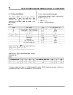
Table 2
5.1 Torque Guidelines
The following table shows the proper torque
requirements for the cap screws and nuts
described. Each type of cap screw and nut is
shown in the following Tables according to the
item number.
Torque Requirement Procedures
All fasteners should be re-torqued according to
the following schedule.
•
After 30 days
•
Every 6 months thereafter
NOTE
Torque values in Table 2 do not apply to air
springs or lower grade fasteners.
Table 2, Cap screw/bolt (Grade 8 UNF) Torque
Requirements **
**Torque values shown apply only to W&C supplied fasteners. If other fasteners are used, follow torque
specifications listed in vehicle manufacturer’s service manual.
Item #
Description
Size
Torque Range (lb.-ft.)
25
Backbone/Upper Kingpin Assembly Nut
7/8”-14
425
26
Tie-Rod End to Tie-Rod Arm Castle Nut
7/8”-14
160-300
28
Stabilizer Shock Nut
3/4”-16
200-250
32 ( Integrated Brake)
Anchor Pin Nut
5/8”-18
175
32 ( Bolt-on Brake)
Attachment Nut
3/4”-16
200 – 225
Draw Key Nut
7/16”-20
30-45
Grease Fitting
1/8” NPT
10
Cross Tube Clamp Nut
5/8”-11
60-80
Stop Screw Lock/Jam Nut
1/2”-13
50-75
Cap screw/bolt Size
3/8”
1/2”
5/8”
3/4”
3/4" (Stabilizer Shock Stud)
7/8”
1”
1 1/8”
Torque minimum ft./lbs.
25
50
150
300
200
500
700
900
Torque maximum ft./lbs.
35
75
200
350
250
550
800
1000
Table 1


