Rev. 1.1
Assembly Instructions - Hand-Spray Valve SMS-15
Page 9 of 18
Walther Systemtechnik GmbH
– D 76726 Germersheim
Telefon: +49 (0)7274-7022-0 Telefax: +49 (0)7274-7022-91
http://www.walther-2000.de
5.2 Mounting and Installation
The valves can be installed in any position. The distance to the application area depends on the desired
application width. You can use round and flat-jet caps. An intermitting operation of the device will cause
natural oscillations; therefore a solid installation is most important. Try to avoid excessive natural oscillations
(transmission from device to valve).
5.3 Hose Mounting
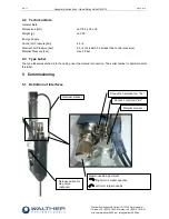
There are three functional hoses which will be connected as follows (see definition of interfaces):
1.
Atomizer air (blue) to ZL
M5
– connection "ZL" - Pos. 2.4
2.
Control air (black) to SL
M5
– connection "SL" - Pos. 2.4
3.
Material (transparent) to M
1/8"-connection "M" - Pos. 2.3
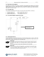
5.4 Connection Diagram (separate controls)
5.5 Adjusting the Device
The stroke adjustment of the needle will be used for setting the material quantity. A left turn of the raster-
needle locking screw will increase the material quantity. A finely ascending precision thread results in a nee-
dle stroke which changes 0.5mm with one turn of the raster head.
IMPORTANT
The maximum turn of the raster-needle locking screw anti-clockwise should not exceed
the noticeable raster steps. This will already exceed the maximum needle stroke ad-
justment.
If you continue turning, the raster-needle locking screw will be dislocated!
IMPORTANT
Nozzle and nozzle needle can be damaged by wrong treatment. Only reduce the mate-
rial flow with emerging material (right turn of adjusting screw). Do not turn adjusting
screw further to the right after closing of the nozzle!
Controls not included in
scope of delivery


