Rev. 1.1
Assembly Instructions - Hand-Spray Valve SMS-15
Page 7 of 18
Walther Systemtechnik GmbH
– D 76726 Germersheim
Telefon: +49 (0)7274-7022-0 Telefax: +49 (0)7274-7022-91
http://www.walther-2000.de
3 Transport
3.1 Packaging
The type of packaging depends on the individual mode of shipping. If not separately contracted, the
packaging is in accordance with the rules and regulations of Walther Systemtechnik GmbH. This rule is in
accordance with the Federal Association for Packaging HPE.
3.2 Tasks before Transport
The following has to be done before transport:
Disconnect all power lines.
The actual transport of the incomplete device and its individual parts requires special care in order to prevent
damages from external forceful impact or careless on- and off-loading. Depending on the mode of
transportation, suitable transport and load securing has to be selected. The incomplete device will be aligned
and leveled by appropriate fastening elements
.
4 Description of Function
4.1 Purpose of the Device
CAUTION
The use of other media can cause functional failures, damages or even the destruction
of the device.
The spray valves of
SMS-15
series are suitable for the application of liquid up to viscous media, such as
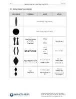
grease, oil, abherents, colors or glues. Major characteristics of the hand-spray valve are the steplessly ad-
justable spray width as well as the integrated spray air valve for pre- and post-spray. And depending on the
viscosity of the applicable medium, the application image can be adjusted individually via the nozzle size or
the atomized air pressure or also the material pressure. Three different hoses are supplying atomized air,
control air and medium.
Spray valve
SMS-15
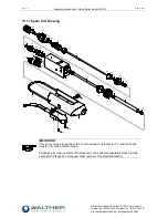
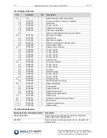
is a pneumatically controlled application device. The air valve (Pos.4.0) is connected
with the needle (Pos.1.6) and receives air supply from the optional 3/2-way magnetic valve. This results in
the opening movement of the air valve (Pos.4.0) so that atomizer air is released (pre-spray). The spring
(Pos.4.4) has to be completely compressed before the air valve (Pos.4.0) will move the needle (Pos.1.6),
and then the material will be discharged from the nozzle. When the control air is turned off or fails, the spring
(Pos.5.0) will initiate the closing movement of the needle; first the needle closes the nozzle and after that the
air valve (post-spray) is locked. Pre- and post-spray are required for keeping the nozzle (Pos.1.1) clean.
The material supply pressure (1/8” connection – Pos.2.3) has to be adapted to the desired spray image and
also to the atomizer air pressure (M5 connection “ZL” – Pos.2.4).
Spraying can be performed as
continuous or intermittent. The control air pulses (M5 connection “SL” –
Pos.2.4) will be directed to the working piston via the 3/2-way magnetic valve (optional).
Depending on the individual area of operation, the control air pressure has to be adapted to the operating
cycles.


