background image


Cleveland, OH 44115-2851                                        New York, NY 10036           

www.powertoolinstitute.org


www.ansi.org


National Safety Council                                              ANSI 01.1 Safety Requirements for   
1121 Spring Lake Drive                                              Woodworking Machines and the   
Itasca, IL 60143-3201                                                  U.S. Department of Labor Relations     
                                                                                       

www.osha.gov


                                          PRODUCT SAFETY                                         

1. 

Serious personal injury may occur if normal safety precautions are overlooked or ignored.   
Accidents are frequently caused by lack of familiarity or failure to pay attention. Obtain 
advice from supervisor, instructor, or another qualified individual who is familiar with this 
machine and its operations. 

2. 

Every work area is different. Always consider safety first, as it applies to your work area.   
Use this machine with respect and caution. Failure to do so could result in serious personal 
injury and damage to the machine. 

3. 

Prevent electrical shock. Follow all electrical and safety codes, including the National 
Electrical Code (NEC) and the Occupational Safety and Health Regulations (OSHA). All 
electrical connections and wiring should be made by qualified personnel only 

4. 


WARNING!

    TO REDUCE the risk of electrical shock. DO NOT use this machine outdoors. 

DO NOT expose to rain. Store indoors in a dry area. 

5. 

STOP using this machine, if at any time you experience difficulties in performing any 
operation. Contact your supervisor, instructor or machine service center immediately. 

6. 

Safety decals are on this machine to warn and direct you to how to protector yourself or 
visitors from personal injury.    These decals MUST be maintained so that they are legible.   

7. 

DO NOT leave the unit plugged into the electrical outlet. Unplug the unit from the outlet when 
not in use and before servicing, performing maintenance tasks, or cleaning. 

8. 


WARNING!

    DO NOT handle the plug or machine with wet hands 

9. 

USE only accessories as described in this manual and recommended by WAHUDA. 

10. 

DO NOT pull the jointer by the power cord. NEVER allow the power cord to come in contact 
with sharp edges, hot surfaces, oil or grease. 

11. 

ALWAYS turn the power switch “OFF” before unplugging the machine. DO NOT unplug the 
machine by pulling on the power cord. ALWAYS grasp the plug, not the cord. 

12. 

REPLACE a damaged cord immediately. DO NOT use a damaged cord or plug.   

13. 

DO NOT use the machine as a toy. DO NOT use near or around children. 

14. 

ENSURE that the machine sits firmly before using. If the machine wobbles or is unstable, 
correct the problem by attaching to a bench top prior to operation. 

15. 

This machine is designed to process wood ONLY. 


Содержание 60170ML-WHD

Страница 1: ...re using machine to avoid serious injury and damage 60170ML WHD 14 Variable Speed Woodworking Mini Lathe with Wired Remote and Digital Readout For technical support email techservices wahudatools com...

Страница 2: ...ram Lists 24 INTRODUCTION This user manual is intended for use by anyone working with this machine It should be kept available for immediate reference so that all operations can be performed with maxi...

Страница 3: ...ight prepaid to WAHUDA s Authorized Service Center for inspection If the warranty claim is considered to be invalid due to exclusions listed above WAHUDA will at your direction dispose of or return th...

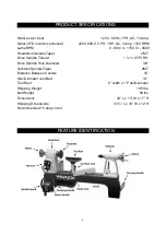
Страница 4: ...adstock Spindle Taper 2MT Drive Spindle Thread 1 x 8 TPI RH Drive Spindle Hole Diameter 3 8 Tailstock Spindle Taper 2MT Distance Between Centers 16 Max Diameter over Bed 14 Tool Rest 6 width x 1 Post...

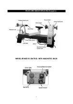
Страница 5: ...5 FEATURE IDENTIFICATION cont WIRED REMOTE CONTROL WITH MAGNETIC BACK...

Страница 6: ...ury including silicosis a serious lung disease cancer and death Avoid breathing the dust and avoid prolonged contact with dust The dust may contain chemicals known to the State of California to cause...

Страница 7: ...r quality job by only performing operations for which the machine was intended WARNING DO NOT stand on a machine Serious injury could result if it tips over or you accidentally contact any moving part...

Страница 8: ...the machine If in doubt DO NOT use it THE USE of extension cords is not recommended for 230V equipment It is better to arrange the placement of your equipment and the installed wiring to eliminate the...

Страница 9: ...ose to rain Store indoors in a dry area 5 STOP using this machine if at any time you experience difficulties in performing any operation Contact your supervisor instructor or machine service center im...

Страница 10: ...ls are stored away from the turning area of the lathe Do not reach over a rotating work piece at any time 26 DO NOT dig in or try to take too large of cut 27 DO NOT leave the lathe running unattended...

Страница 11: ...u are not sure the tool is properly grounded WARNING Electrocution or fire could result if this machine is not grounded properly or if the electrical configuration does not comply with local and state...

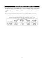
Страница 12: ...or have it repaired by a qualified person before using it Protect your extension cords from sharp objects excessive heat and damp or wet areas MINIMUM RECOMMENDED GAUGE FOR EXTENSION CORDS AWG 115 VOL...

Страница 13: ...coat of good quality paste wax over the lathe bed to allow the banjo and tailstock to glide smoothly across the bed and to prevent corrosion Make sure to buff out the wax before assembly Compare the i...

Страница 14: ...he remaining 5 use the parts diagram and parts list at the back of this manual for assistance CARRYING HANDLES 1 Locate the 2 carrying handles and 4 screws E on previous page and attach them to each e...

Страница 15: ...ed ELECTRONIC INVERTER CONTROL UNIT The electronic Variable Frequency Drive VFD inverter control unit by Delta Electronics located on the rear of the machine provides constant torque throughout the sp...

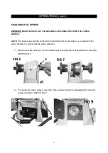
Страница 16: ...THE POWER SOURCE 1 Position the banjo A on the bed by loosening the banjo lock handle B and sliding the banjo to the desired position Tighten handle B to lock in place SEE FIG 5 2 Adjust the height o...

Страница 17: ...eed pulley combination is furthest from the faceplate i e smallest motor pulley diameter to largest spindle pulley diameter 1 Open the access panel A on the headstock by loosening the access panel loc...

Страница 18: ...stock pulleys Rotate the spindle by hand to make sure the belt is seated vertically on the selected pulleys Once verified press down on the motor handle B in FIG 10 above to apply tension to the belt...

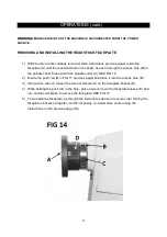
Страница 19: ...To re insert the drive center place it in the hole in the faceplate and while using a block of wood and a hammer tap the drive center to set it in the headstock REMOVING AND INSTALLING THE LIVE CENTE...

Страница 20: ...e spindle collar C SEE FIG 14 2 Locate the push rod B in FIG 11 previous page and place it into the access hole B 3 Using a hex wrench loosen the two set screws D on the faceplate bosses E 4 While hol...

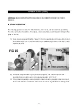
Страница 21: ...pen the access panel FIG 6 7 page 17 Turn the headstock until the pre drilled hole in the headstock A lines up with one of the 24 pre drilled hole positions on the index pulley SEE FIG 15 16 2 Locate...

Страница 22: ...and tool rest etc MONTHLY Check the belt tension and adjust if necessary See pages 17 and 18 for instructions Check for any build up of wood shavings on the motor and pulleys and clean if necessary U...

Страница 23: ...cord Reduce load on circuit Increase wire sizes or reduce length of the circuit Motor overheats Motor overloaded during operation Air circulation through the motor restricted Reduce load on motor tak...

Страница 24: ...24 PARTS...

Страница 25: ...25 PARTS cont...

Страница 26: ...60170 12B Cover 1 60170 13 Cap Screw 1 4 1 2 1 60170 14 Cap Screw 1 4 1 4 60170 15 Spring Washer 1 4 4 60170 16B Head Stock 1 60170 17 Bearing 6004VV 1 60170 18 Wave washer BWW629 1 60170 19 Handwhee...

Страница 27: ...70 43 Hex head Screw 5 16 x1 1 4 1 60170 44 Washer 5 16 3mm 1 60170 45 Washer 1 4 2 60170 46 Cap Screw 1 4 x5 8 2 60170 47 Black handle protector 1 60170 48 Motor plate 1 60170 49 Nylon Nut 5 16 18UNC...

Страница 28: ...r PG11 1 60170 77 Wire clamp ACC 1 5 2 60170 78 Readout board 1 60170 79 R P M readout I C 1 60170 79 1 Single wire 1 60170 79 3 Single wire 1 60170 79 5 Digital readout power wire 1 60170 79 6 Digita...

Страница 29: ...10 24X3 4 1 60170 97 Hex head screw 3 8 x2 4 60170 99 Nut 10 24 4 60170 100 Foot pad Nut 3 8 4 60170 101 Flat screw 3 16 x1 2 4 60170 102 Plate 1 60170 103 Hinge 1 60170 104 Face Plate Wrench 1 60170...

Страница 30: ...30 60170 116 Cord Snap Ring ACC 2 5 2 60170 117 Tapping Screw M3x8 3 60170 118 Inverter cover 1 60170 119 Round Head Screw 10 24UNC 1 4 4...

Страница 31: ...31 WIRING DIAGRAM...

Страница 32: ...32...

Отзывы: