background image

WAGO-I/O-SYSTEM 750 

Appendix  121 

750-657 IO-Link Master 


Manual 


Version 1.0.2, valid from FW/HW-Version 02/01 


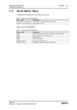
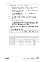
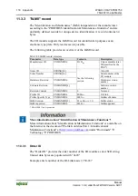
In generally, the following information for an IO-Link device is saved in the I/O 
module: 

Table 114: IOL-M Port Configuration, Data 

Parameter 

Data type 

Description 

Revision ID 

UNSIGNED8 

Revision ID 

Vendor ID 

UNSIGNED16 

Vendor ID 

Device ID 

UNSIGNED24 

Device ID 

Serial Number 

STRING[16] Serial 

Number 

Hardware Revision 


Hardware Revision 

PD Input 

UNSIGNED8 

Length of the process input data 

PD Output 

UNSIGNED8 

Length of the process output data 


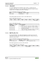
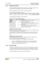
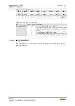
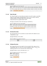
11.3.4.4.1 Revision ID 

Table 115: Revision-ID, Structure 

Bit 7 

… 

Bit 4 

Bit 3 

… 

Bit 0 

Major Revision 

Minor Revision 


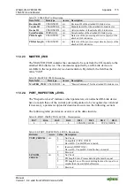
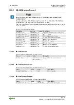
11.3.4.4.2 Index CAP 1  

Table 116: Master Configuration, Index CAP 1 

Name 

Access 

Value 

Description 

Index CAP 1 

ro 

0xFF (255) 

Index of Client access points 


Содержание WAGO-I/O-SYSTEM 750 Series

Страница 1: ...29289866_0 doc 64941 1 Manual WAGO I O SYSTEM 750 IO Link Master 750 657 Version 1 0 2 valid from FW HW Version 02 01 Pos 3 Alle Serien Allgemeine Module Hinweise zur Dokumentation Impressum für Standardhandbücher allg Angaben Anschriften Telefonnummern und E Mail Adressen 3 mod_1219151118203_21 doc 21060 1 ...

Страница 2: ... 55 Fax 49 0 571 8 87 85 55 E Mail support wago com Every conceivable measure has been taken to ensure the accuracy and completeness of this documentation However as errors can never be fully excluded we always appreciate any information or suggestions for improving the documentation E Mail documentation wago com We wish to point out that the software and hardware terms as well as the trademarks o...

Страница 3: ...d Devices 12 2 2 Safety Advice Precautions 13 3 The IO Link Technology 15 4 Device Description 16 4 1 View 19 4 2 Connectors 21 4 2 1 Data Contacts Internal Bus 21 4 2 2 Power Jumper Contacts Field Supply 22 4 2 3 CAGE CLAMP Connections 23 4 3 Display Elements 24 4 4 Schematic Diagram 25 4 5 Technical Data 26 4 5 1 Device Data 26 4 5 2 Supply 26 4 5 3 Communication 26 4 5 4 IO Link Ports 27 4 6 Ap...

Страница 4: ...ia the Mailbox 68 10 2 1 Diagnostic Telegram 68 10 3 Event Codes 70 10 3 1 Event Codes of the IO Link Masters 70 10 3 2 Event Codes of Attached Devices 73 11 Appendix 75 11 1 Communication Services of the IO Link Master 75 11 1 1 Mailbox 2 0 Transmission Method 75 11 1 1 1 Message 75 11 1 1 2 Transmission channel 76 11 1 1 2 1 The Handshake Byte 77 11 1 1 3 Communication Phases 78 11 1 1 3 1 Synch...

Страница 5: ...10 11 3 1 6 IOLM_PAB_STRUCT 111 11 3 2 IOL M Port Configuration record 113 11 3 2 1 PORT_CONFIG 113 11 3 2 2 COMP_DATA 114 11 3 2 3 MASTER_CMD 115 11 3 2 4 PORT_INSPECTION_LEVEL 115 11 3 2 5 PARAM_SERV_MODI 116 11 3 2 6 IOLD_FEATURE 116 11 3 2 7 IOLD_RESERVED 117 11 3 3 I M0 record 118 11 3 3 1 Order ID 118 11 3 3 2 Serial Number 119 11 3 3 3 Hardware Revision 119 11 3 3 4 Software Revision 119 11...

Страница 6: ...E 126 11 4 1 2 1 GSD GSE File 126 11 4 1 2 1 1 Simple Configuration Record 127 11 4 1 2 1 2 Extended Configuration Record 128 11 4 1 3 Configuring with Function Blocks 131 11 4 1 3 1 SIMATIC Step 7 131 11 4 1 3 2 PROFIBUS Master general 132 11 4 1 4 Diagnosis when Using a PROFIBUS Coupler 133 11 4 2 CANopen 139 11 4 2 1 PDO Mapping 139 11 4 3 sercos 142 List of Figures 144 List of Tables 146 Ende ...

Страница 7: ...Link Master of the WAGO I O SYSTEM 750 series from FW HW Version 02 01 Pos 11 Serie 750 WAGO I O SYSTEM Hinweise zur Dokumentation Hinweise Achtung Hinweis zur Dokumentation Busklemmen 750 xxxx 4 mod_1237986979656_21 doc 29023 1 The I O module 750 657 shall only be installed and operated according to the instructions in this manual and in the manual for the used fieldbus coupler controller Conside...

Страница 8: ...Pos 12 4 4 Alle Serien Allgemeine Module Wichtige Erläuterungen Sicherheits und sonstige Hinweise Vorsicht Vorsicht _Warnung vor Personenschäden allgemein_ Erläuterung 13 mod_1343310028762_21 doc 101038 1 Personal Injury Indicates a low risk potentially hazardous situation which if not avoided may result in minor or moderate injury Pos 12 4 5 Alle Serien Allgemeine Module Wichtige Erläuterungen Si...

Страница 9: ...Manual Version 1 0 2 valid from FW HW Version 02 01 Additional Information Refers to additional information which is not an integral part of this documentation e g the Internet Pos 12 5 Dokumentation allgemein Gliederungselemente Seitenwechsel 3 mod_1221108045078_0 doc 21810 1 ...

Страница 10: ...entions Table 2 Font conventions Font type Indicates italic Names of paths and data files are marked in italic type e g C Programme WAGO I O CHECK Menu Menu items are marked in bold letters e g Save A greater than sign between two names means the selection of a menu item from a menu e g File New Input Designation of input or optional fields are marked in bold letters e g Start of measurement range...

Страница 11: ...e 750 WAGO I O SYSTEM Wichtige Erläuterungen Personalqualifikation 750 xxxx 3 mod_1224061208046_21 doc 24063 3 1 2 1 2 Personnel Qualifications All sequences implemented on Series 750 devices may only be carried out by electrical specialists with sufficient knowledge in automation The specialists must be familiar with the current norms and guidelines for the devices and automated environments All ...

Страница 12: ...nd der Geräte Überschrift 3 und Inhalt 3 mod_1221060446109_21 doc 21723 3 1 2 1 4 Technical Condition of Specified Devices The components to be supplied Ex Works are equipped with hardware and software configurations which meet the individual application requirements WAGO Kontakttechnik GmbH Co KG will be exempted from any liability in case of changes in hardware or software as well as to non comp...

Страница 13: ...efahr Gefahr Unfallverhütungsvorschriften beachten 6 mod_1260180657000_21 doc 46735 1 Pos 15 10 4 Alle Serien Allgemeine Module Wichtige Erläuterungen Sicherheits und sonstige Hinweise Gefahr Gefahr Auf normgerechten Anschluss achten 6 mod_1260180753479_21 doc 46739 1 Pos 15 11 1 Alle Serien Allgemeine Module Wichtige Erläuterungen Sicherheits und sonstige Hinweise Achtung Achtung Defekte oder bes...

Страница 14: ...ty of connection lines Avoid reverse polarity of data and power supply lines as this may damage the devices involved Pos 15 11 6 Alle Serien Allgemeine Module Wichtige Erläuterungen Sicherheits und sonstige Hinweise Achtung Achtung Elektrostatische Entladung vermeiden 6 mod_1260181364729_21 doc 46759 1 Avoid electrostatic discharge The devices are equipped with electronic components that you may d...

Страница 15: ...Communication occurs via serial point to point links in standard 3 wire technology Both data and diagnostic information as well as power supply are carried over the serial IO Link interface simultaneously IO Link IO Link device IO Link master 1 4 2 3 DI DO C Q L L C Q 4 8 38 4 230 kbit s Figure 1 3 wire connection technology based on Physics 2 of the IO Link specification 1 0 0 Configuration of IO...

Страница 16: ...parameterization and diagnostic data The process data width of an IO Link device can be between one bit e g simple switches and 32 bytes e g complex sensors actuators Transfer is based on 24V levels Transfer is half duplex i e data is sent and received one after the other Standard sensor cables can be used Shielding is not required WAGO I O CHECK function blocks or PROFIBUS GSD GSE can be used to ...

Страница 17: ...r Version PROFIBUS Fieldbus coupler 750 333 16 20 03 750 341 08 09 02 750 342 17 07 06 750 352 02 02 03 Fieldbus coupler 750 354 01 01 01 750 841 19 11 02 750 842 18 13 06 750 843 02 10 06 750 871 07 05 02 750 872 03 04 02 750 873 03 04 02 750 880 02 04 03 750 880 0025 0001 03 04 03 750 880 0025 0002 03 04 03 750 881 02 02 03 750 882 02 05 03 750 884 03 06 03 ETHERNET Programmable fieldbus control...

Страница 18: ...2 10 12 758 0870 0000 0111 Firmware revision 01 01 26 05 Internal bus FW revision 01 02 10 12 758 0875 0000 0111 Firmware revision 01 01 26 05 Internal bus FW revision 01 02 10 12 WAGO IPC IPC 758 0876 0000 0112 Firmware revision 01 01 26 05 Internal bus FW revision 01 02 10 12 Restriction on CANopen couplers 750 347 and 750 348 With a process data length of 4 bytes the byte sequence is turned for...

Страница 19: ...le Überschriften für alle Serien Gerätebeschreibung Ansicht Überschrift 2 4 mod_1240984217343_21 doc 31958 2 1 4 1 View Pos 26 Serie 750 WAGO I O SYSTEM Gerätebeschreibung Ansicht Sonderklemmen Ansicht 750 0657 4 mod_1243579502125_21 doc 34450 1 13 750 657 1 2 3 4 5 6 7 8 14 9 10 11 12 13 14 15 16 1 8 7 5 3 3 7 11 2 4 6 9 11 12 13 10 14 Figure 3 View ...

Страница 20: ...LAMP connections L 0 V Device Description Connections 7 Power jumper contact L 24 V Device Description Connections 8 4 12 CAGE CLAMP connections Field supply 24 V Device Description Connections 9 Release clip Mounting Insert and remove device 10 5 13 CAGE CLAMP connections Field supply 0 V Device Description Connections 11 Power jumper contact L 0 V Device Description Connections 12 6 14 CAGE CLAM...

Страница 21: ... cleaning gold spring contacts Figure 4 Data contacts Pos 30 2 Serie 750 WAGO I O SYSTEM Wichtige Erläuterungen Sicherheits und sonstige Hinweise Achtung Achtung Busklemmen nicht auf Goldfederkontakte legen 7 mod_1266318463636_21 doc 50695 1 Do not place the I O modules on the gold spring contacts Do not place the I O modules on the gold spring contacts in order to avoid soiling or scratching Pos ...

Страница 22: ... spring contacts Table 5 Power jumper contacts Connection Type Number Function 1 Blade contact 2 Infeed of the field supply voltage UV and 0 V 1 2 1 2 Figure 5 Power jumper contacts 2 Spring contact 2 Forwarding of the field supply voltage UV and 0 V Pos 33 3 Serie 750 WAGO I O SYSTEM Wichtige Erläuterungen Sicherheits und sonstige Hinweise Achtung Achtung Maximaler Strom Leistungskontakte 10 A 3 ...

Страница 23: ...7 Dokumentation allgemein Gliederungselemente Seitenwechsel 3 mod_1221108045078_0 doc 21810 1 Table 6 Connections Termination Channel Designation Function 1 1 C Q 1 IO Link Port 1 2 L Power supply DC 24 V 3 L Power supply 0 V 4 24 V Field supply 24 V 5 0 V Field supply 0 V 6 2 C Q 2 IO Link Port 2 7 L Power supply DC 24 V 8 L Power supply 0 V 9 3 C Q 3 IO Link Port 3 10 L Power supply DC 24 V 11 L...

Страница 24: ... status C Q 2 Off SIO DI DO Low state 3 Off reserved 4 Off reserved 5 Off reserved 6 Off reserved 7 Off reserved Green blinking Parameterization active 8 Operating status IO Link master Off Parameterization inactive IO Link Device connected IO Link Data OK Green SIO DI DO High state Green blinking Start up or parameterization duration 3 s Red blinking Error no valid process data for C Q 3 IO Link ...

Страница 25: ...Diagram Pos 42 Serie 750 WAGO I O SYSTEM Gerätebeschreibung Schematische Schaltbilder Sonderklemmen Schematisches Schaltbild 750 0657 5 mod_1244033618406_21 doc 34855 1 1 2 7 8 3 4 5 6 9 10 13 11 12 15 14 16 SPI SPI 24 V 0 V C Q Status C Q 1 24 V 0 V C Q 2 C Q 3 C Q 4 750 657 22 nF 1 nF 22 nF 24 V 24 V 24 V 24 V 0 V 0 V 0 V 24 V 0 V 0 V 0 V 0 V 24 V 24 V Figure 8 Schematic Diagram Pos 43 Dokumenta...

Страница 26: ...tion storage 95 without condensation Degree of protection IP 20 4 5 2 Supply Table 9 Technical Data Supply Voltage supply system voltage 5 V via internal data bus 24 V via power jumper contacts Current consumption system voltage typ 5 V DC 40 mA Current consumption max 24 V DC 1250 mA 50 mA internal power supply field side 4 x 100 mA output current from C Q 4 x 200 mA supply voltage L of the devic...

Страница 27: ...ine length max 20 m Sensor supply UV DC 24 V Nominal current per port L 200 mA Maximum current per port C Q 100 mA Short circuit protected C Q yes Short circuit current max C Q 450 mA Operation mode SIO DI Input type 1 acc to norm EN 61131 2 2007 Signal current 0 6 mA typ Signal voltage 0 5 V Signal current 1 7 mA typ Signal voltage 1 15 V Operation mode DO Output voltage DC 24 V Output current ma...

Страница 28: ...he minimum cable cross section Maintain the recommended minimum cable cross section For 20 m cable length select a minimum cross section of 0 34 mm You can use unshielded cable Use binary sensors with PNO or push pull output Binary sensors with PNP output or push pull output can be connected to an IO Link master in operating modes DI and DO but not connected to an NPN output Pos 46 Dokumentation a...

Страница 29: ... Allgemeine Module Zulassungen Standardzulassungen CE Konformitätskennzeichnung 3 mod_1224494777421_21 doc 24276 1 Conformity Marking Pos 51 Alle Serien Allgemeine Module Zulassungen Standardzulassungen cULus UL508 3 mod_1224055013140_0 doc 24020 1 CULUS UL508 Pos 52 Dokumentation allgemein Gliederungselemente Leerzeile 3 mod_1224662755687_0 doc 24460 1 Pos 53 Serie 750 WAGO I O SYSTEM Gerätebesch...

Страница 30: ... 2 Pos 59 Alle Serien Allgemeine Module Normen und Richtlinien EMV CE Störfestigkeit EN 61000 4 3 7 mod_1272369238111_21 doc 55837 1 EMC CE Immunity to interference acc to EN 61000 4 3 Pos 60 Alle Serien Allgemeine Module Normen und Richtlinien EMV CE Störfestigkeit EN 61000 4 4 7 mod_1272369382207_21 doc 55843 1 EMC CE Immunity to interference acc to EN 61000 4 4 Pos 61 Alle Serien Allgemeine Mod...

Страница 31: ...operating modes IO Link or SIO Standard Input Output DI Digital Input default setting DO Digital Output and Inactive The respective operating mode can be set separately for each port of the IO Link master The data between the IO Link master and attached devices is exchanged cyclically via the IO Link interface and depending on the source processed accordingly and transferred via the internal bus P...

Страница 32: ...s I M 0 4 Information about the IO Link master itself IOL M Directory This information is read only Records of the attached IO Link devices ISDU according to the IO Link specification The IO Link specific records are described in detail in the appendix section IO Link Master tables More information about the Indexed Service Data Unit ISDU is available in the section Parameter Access via ISDU Figur...

Страница 33: ...ss image for example Mailbox size 2 bytes Process image Pi size Input data Output data S0 Status byte C0 Control byte FC0 Acyclic channel Register byte 0 FC0 Acyclic channel Register byte 0 MB0 Mailbox Byte Register byte 1 MB0 Mailbox byte Register byte 1 4 Byte SIO SIO byte SIO SIO byte D0 Data byte 0 D0 Data byte 0 6 Byte D1 Data byte 1 D1 Data byte 1 D2 Data byte 2 D2 Data byte 2 8 Byte D3 Data...

Страница 34: ...register Register number reserved Status byte Table 14 Status byte Status byte Bit 7 Bit 6 Bit 5 Bit 4 Bit 3 Bit 2 Bit 1 Bit 0 0 GEN_ ERR PORT4_ ERR PORT3_ ERR PORT2_ ERR PORT1_ ERR IOLM_ ERR INT_ ERR 1 Res Register number 0 Mailbox active Bit 7 1 Register communication active 0 No error GEN_ERR 1 Error is pending Set when one of the bits 0 5 1 0 The device attached to port 4 is not in the fault c...

Страница 35: ...nputs or outputs to and from the control The following table provides an overview of the SIO byte Table 15 SIO Byte SIO byte Bit 7 Bit 6 Bit 5 Bit 4 Bit 3 Bit 2 Bit 1 Bit 0 0 0 0 0 SIO3 SIO2 SIO1 SIO0 0 Process data of digital port 4 logical 0 SIO3 1 Process data of digital port 4 logical 1 0 Process data of digital port 3 logical 0 SIO2 1 Process data of digital port 3 logical 1 0 Process data of...

Страница 36: ...ontrol status byte the Mailbox bytes and the SIO byte If the selected internal bus data width is more than the set Mailbox size control status and SIO byte another data storage area is available in addition to using the SIO byte in which process data is transferred cyclically from attached IO Link devices see the following figure Four segments can be configured in this area one segment for each po...

Страница 37: ...ata width is set to 12 or 8 bytes and the Mailbox size is 2 bytes for example the data storage area available is reduced for the cyclical data accordingly With a setting of 4 bytes only the SIO byte is available for cyclic data Segment size process data width of the IO Link device The segment size of a port segment does not have to match the process data width of the attached IO Link device Asymme...

Страница 38: ...nused 0x00 Unused 0x00 Port 1 2 3 4 Segment size process data width of the IO Link device If the segment size is equal to or greater than the process data width of the IO Link device the excess bytes of the input data are populated with 0x00 The excess bytes are ignored in the output direction Segment size process data width of the IO Link device If the segment size is smaller than the process dat...

Страница 39: ... carefully to prevent injury Pos 71 3 Serie 750 WAGO I O SYSTEM Wichtige Erläuterungen Sicherheits und sonstige Hinweise Achtung Achtung Busklemmen in vorgegebener Reihenfolge stecken 6 mod_1256194177073_21 doc 43429 1 Connect the I O modules in the required order Never plug I O modules from the direction of the end terminal A ground wire power contact which is inserted into a terminal without con...

Страница 40: ...tion Grounding Ground Conductor in manual System Description WAGO I O SYSTEM 750 Pos 71 9 Alle Serien Allgemeine Module Wichtige Erläuterungen Sicherheits und sonstige Hinweise Achtung Achtung Arbeiten an Geräten nur spannungsfrei durchführen 6 mod_1256193963573_21 doc 43426 1 Perform work on devices only if the system is de energized Working on devices when the system is energized can damage the ...

Страница 41: ...r to the previous or possibly subsequent I O module are established Pos 71 11 Serie 750 WAGO I O SYSTEM Montieren Busklemme entfernen 4 mod_1239169375203_21 doc 30334 3 1 7 2 2 Removing the I O Module 1 Remove the I O module from the assembly by pulling the release tab Figure 14 Removing the I O module Electrical connections for data or power contacts are disconnected when removing the I O module ...

Страница 42: ...more than one conductor at one single connection If more than one conductor must be routed to one connection these must be connected in an up circuit wiring assembly for example using WAGO feed through terminals Exception If it is unavoidable to jointly connect 2 conductors then you must use a ferrule to join the wires together The following ferrules can be used Length 8 mm Nominal cross section m...

Страница 43: ...ion block WagoLib_IO_Link lib of the WAGO I O PRO library Configuration software using device description files e g PROFIBUS GSD GSE see appendix section Configuration Using PROFIBUS GSD GSE Configuration and parameterization via WAGO I O CHECK and WAGO I O PRO make use of acyclic communication via the Mailbox and register communication For access via the Mailbox a parameter access service is prov...

Страница 44: ...y configure and parameterize the IO Link master Configuration of node internal transmission bus Parameterization of the operating modes of the IO Link master Diagnosis of the IO Link master Importing of the IO Link specific device description fields IODDs Display Configure and Parameterize IO Link devices Diagnosis of IO Link devices Additional Information You receive the WAGO I O CHECK on a CD RO...

Страница 45: ...sion 02 01 9 1 1 User Interface The user interface is divided into the following areas Figure 17 IO Link master user interface 1 Title bar 2 Toolbar 3 Master Configuration Port Configuration und Module ID tabs diagnostic and event message at the bottom These areas will be explained in more detail in the following sections ...

Страница 46: ...n with the IO Link master Reads the current parameters of the page displayed from the IO Link master and displays them in the window Another menu item is available in the context menu Read parameters on current page Read parameters on current page Read Read all Parameters Read all parameters Writes the current parameters of the page displayed to the I O module Additional menu items are available i...

Страница 47: ...x Process image total size 1 SIO byte 1 control status byte The Mailbox size is 2 bytes by default To increase the Mailbox size during the configuration enter the new required value manually in the respective Length input field or use the arrow keys to select the value By entering a higher value in the Length field e g 6 bytes the data throughput is increased and the configuration operations are e...

Страница 48: ... image size Table 18 Setting the process image size Option Description Process Image Size 4 6 8 10 12 16 20 or 24 Byte Setting the process image size Mailbox Offset Byte Offset for the Mailbox start can be changed Size Byte Mailbox size can be changed Ok Save the process image size set Cancel Close window without saving Help Opens the WAGO I O CHECK online help ...

Страница 49: ...guration and Parameterization 49 750 657 IO Link Master Manual Version 1 0 2 valid from FW HW Version 02 01 9 1 1 2 2 Options Click the Options button to set actions at application startup exit and timeout Figure 20 Set options ...

Страница 50: ...he Save button Load configuration file on startup Do not load a configuration file Actions On Application Exit Restart the fieldbus coupler controller after closing the configuration dialog Software reset on program exit Do not restart after closing the configuration dialog Communication Timeouts RS 232 ___ sec TCP IP ___ sec Time during which a response is expected after sending the command via R...

Страница 51: ...rors The toolbar in the Events dialog includes the following buttons Figure 21 Toolbar buttons Table 20 Toolbar buttons Button Function Description Close Closes the message window Refresh Refreshes the list of messages Show hide data column Shows hides the Data column Save Saves all messages previously logged to a file First Entry Go to the first entry Last Entry Go to the last entry Clear List Cl...

Страница 52: ...ilbox events Option Description Timestamp Timestamp of the Mailbox events 0 Acyclic channel Mbx No 1 2 3 4 Fragmentation service Protocol ID 0 IOL_PD 1 IOL_CALL ProtID 2 IOL_DIAG Direction Data direction Received Sent Port Master or device FI Index Specification of the record to be accessed see section FI_Index State Status Init Sync Ready Done Index see table Access to Data Areas 0x100 IOL M Basi...

Страница 53: ... Instance Event instance 0 Unknown 1 Physical layer 2 Data link layer 3 Application layer 4 Application Event Code Event code hexadecimal see table Event Codes of the IO Link Masters Description Description of the diagnostic message or event IOLM Error IOL master error code see section Error Messages IOLD Error IOL device error code see section Error Messages FI Index Specification of the record t...

Страница 54: ... nehmen Parametrieren mit WAGO I O CHECK Konfigurieren und Parametrieren mit WAGO I O CHECK 750 0657 nach Mailbox Events 10 mod_1312360765276_21 doc 75688 4454 1 9 1 1 3 Register Master Configuration The base configuration of the IO Link master appears in the Master Configuration tab In addition you can set the fragmentation for the ports Figure 24 Register Master Configuration ...

Страница 55: ...tion Mode fragmented Enable fragmentation of the respective port Modus Port x not fragmented Disable fragmentation of the respective port Segmentation Offset in the Input Output area is automatically calculated in bytes from the port lengths entered That the total process image size is not exceeded is checked The total process image size is compared to the process image size from the respective IO...

Страница 56: ...ort 3 Segment Port 3 Segment Port 3 Segment Port 3 Segment Port 4 Segment Port 4 Segment Port 4 Segment Port 4 Segment Port 4 Segment Port 4 Segment Port 4 Unused 0x00 Unused 0x00 Unused 0x00 Segment length Size 3 Size 2 Size 5 Size 7 A few rules must be followed during segmentation The smallest value for Offset is 4 The first 4 bytes of the internal bus process image are already occupied by the s...

Страница 57: ...ed to each of the 4 ports and each attached IO Link device Save IODD files in a specific directory So that IODD files are displayed under Port Configuration save them in the following path For Windows XP C Documents and Settings All Users Common Files WAGO Software For Windows 7 C Users Public Documents WAGO Software Only assign the IODD when the IO Link master is not connected If the IO Link mast...

Страница 58: ...58 Configuration and Parameterization WAGO I O SYSTEM 750 750 657 IO Link Master Manual Version 1 0 2 valid from FW HW Version 02 01 Figure 25 Register Port Configuration ...

Страница 59: ...ain If unsuccessful the output remains off Inactive The port is disabled and ignored by the internal device software Transfer rate Display of the transfer rate and COM port e g 38 4 kbit s COM2 Enable port diagnosis via the Mailbox Enable diagnosis over mailbox Disable port diagnosis via the Mailbox IODD Select the device description file IODD the Connect button may not be active Show Device Displ...

Страница 60: ...ose The process data lengths of the IO Link master must be equal to or smaller than the buffer size which provides the I O module for the IO Link device Parameter Server Mode Enable Parameter Server Parameter server enabled factory setting Disable Parameter Server Parameter server disabled Disable Upload Prevents parameter upload The upload request of the IO Link device is suppressed by the I O mo...

Страница 61: ... have been changed This occurs either remotely via the bus or locally on the device Application parameter download When uploading to the IO Link device the master checks the identity of the device DeviceID VendorID SerialNumber When successful the parameter server synchronizes the parameters For devices without ISDU support parameters are always downloaded For devices with ISDU support parameters ...

Страница 62: ...s opened by clicking Show Device button Information from the respective IODD of the attached devices appears in this window Figure 26 IODD data of the respective ports The entries of the displayed menus on the left side and the displayed content are IODD specific and vary by each device The buttons above the product image are part of the IODD interpreter which is integrated in WAGO I O CHECK These...

Страница 63: ...isplay of the instance record online shown in green and the device record offline shown in gray 4 Load instance record 5 Save instance record 6 Upload device record from the device to the instance record 7 Download instance record to the device record 8 Enable disable direct mode All values are saved directly when enabling When disabling direct mode the values must be individually saved by clickin...

Страница 64: ...nk Master Manual Version 1 0 2 valid from FW HW Version 02 01 9 1 1 5 Register Module ID Information about the IO Link master appears in the Module ID tab In addition to reading the I M0 record there is read write access to records I M1 to I M4 Figure 27 Register Module ID ...

Страница 65: ... the installation date Tag Function 2 Data storage area ASCII format for free use Can be used for e g device names or location information I M2 Record Installation Date Data storage area ASCII format for free use Can be used for e g saving the installation date I M3 Record Descriptor Data storage area ASCII format for free use Can be used for e g saving the installation date I M4 Record Signature ...

Страница 66: ...locks In addition to configuring the IO Link master communication is also possible via parameter access service IOL_CALL see appendix section Mailbox 2 0 Transmission Method with attached IO Link devices with which the IO Link devices can be configured and parameterized IO Link specific diagnostic messages can also be displayed If process data of an IO Link device is fragmented the data can be def...

Страница 67: ...us byte Bit 7 Bit 6 Bit 5 Bit 4 Bit 3 Bit 2 Bit 1 Bit 0 0 GEN_ ERR PORT4_ ERR PORT3_ ERR PORT2_ ERR PORT1_ ERR IOLM_ ERR INT_ ERR 1 Res Register number of the request mirrored 0 Mailbox active Bit 7 1 Register communication active 0 No error GEN_ERR 1 Error is pending Set when one of the bits 0 5 1 0 The device attached to port 4 is not in the fault condition PORT4_ERR 1 The device attached to por...

Страница 68: ...determined by the function profile for IO Link which is defined for PROFIBUS in IO Link Integration Part1 2812 A diagnosis is transferred via the Mailbox using the IOL_DIAG diagnostic service For diagnostic purposes the IO Link master provides FIFO memory for 40 diagnostic messages An FIFO is a buffer in which the first element in the queue First In is also processed first First Out If the memory ...

Страница 69: ...ction 0x00 IO Link master 0x01 Port 1 0x02 Port 2 0x03 Port 3 0x04 Port 4 Channel Number 0x05 0xFF Reserved Bit 7 Bit 6 Event mode 0x0 Reserved 0x1 Single Shot 0x2 Event disappears 0x3 Event appears Bit 5 Bit 4 Event type 0x0 Reserved 0x1 Information 0x2 Warning 0x3 Error Bit 3 SOURCE 0 Device application remote 1 Master application local Event Qualifier Bit 2 Bit 0 Event instance 0x0 Unknown 0x1 ...

Страница 70: ... Error Code Possible cause s Possible response s Event code PARAMETER_ERROR from an attached IO Link device for which there is no detailed information 6320 E Single PDU checksum error I O module attempts to reconnect 8CA2 E Come Go 9 IO Link connection interrupted 8CB0 E Come Go 6 Connection error or removal of an IO Link device 1 Check IO Link connection 2 Check IO Link device Port configuration ...

Страница 71: ...quest does not match the ID in the record 8CBC W Single Check vendor ID Data volume larger than available memory resources of the EEPROM 8CBD W Single Contact WAGO Support Error uploading to the parameter server 8CBE W Single Checksum error during the ISDU transfer error in the ISDU telegram Check ISDU telegram Error downloading from the parameter server 8CBF W Single Checksum error during the ISD...

Страница 72: ...n the internal bus process data 2 SIO byte and port segment have a size of 0 and port is in DI DO or SIO operating mode 8CC7 W Single 1 Change segment size to process data width 2 Change SIO byte to length 1 If a port specific diagnosis is disabled this event appears 8CC8 N Single New IO Link device connected FF21 N Single IO Link connection interrupted FF22 N Single Device removed or connection e...

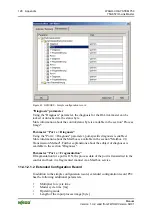
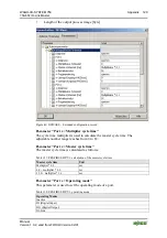
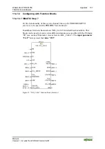
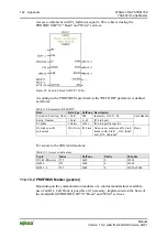
Страница 73: ...4 E 5011 Non volatile memory loss Check batteries 4 E 5012 Batteries low exchange batteries 2 W 5013 50FF Reserved 5100 General power supply fault Check availability 4 E 5101 Fuse blown open Exchange fuse 5102 510F Reserved 5110 Primary supply voltage over run Check tolerance 2 W 5111 Primary supply voltage under run Check tolerance 2 W 5112 Secondary supply voltage fault Port Class B Check tolera...

Страница 74: ...e required Cleaning 1 N 8C41 Maintenance required Refill 1 N 8C42 Maintenance required Exchange wear and tear parts 1 N 8C43 8C9F Reserved 8CA0 8DFF Manufacturer vendor specific 8E00 AFFF Reserved B000 BFFF Reserved for profiles C000 FEFF Reserved FF00 FFFF SDCI specific Event codes N Notification W Warning E Error Device State 0 Device is OK Device State 1 Maintenance Required Device State 2 Out ...

Страница 75: ... based data and commands with no or little real time requirement cyclic transmission is intended for transmission of device data as close to real time as possible To also transfer larger data volumes with smaller data widths of a port segment a cyclic fragmentation service is available 11 1 1 Mailbox 2 0 Transmission Method Mailbox 2 0 defines a service for full duplex transport via a defined chan...

Страница 76: ...meaning 11 1 1 2 Transmission channel To transfer a message over a narrow channel synchronization between sender and receiver is required Therefore the transmission channel is divided into a synchronization part and a data part For synchronization a so called handshake byte HB is defined The handshake byte occupies the first byte of the transmission channel while part of the message is always deli...

Страница 77: ...ure of the handshake byte Table 36 Structure of the handshake byte Handshake byte Bit 7 Bit 6 Bit 5 Bit 4 Bit 3 Bit 2 Bit 1 Bit 0 Status Control Response Command C T T 0x0 C T T 0x0 The following figure shows the basic use of the handshake byte Upstream Downstream Status Control Status Control Status Control Status Control Handshake Handshake Sender Handshake Handshake Sender Control IO Link maste...

Страница 78: ... as command acknowledgement mode In command acknowledgement mode the handshake byte appears as follows Status nibble Control nibble Bit 3 Bit 2 Bit 1 Bit 0 Bit 3 Bit 2 Bit 1 Bit 0 0 Acknowledgement 0 Acknowledgement The Control nibble is used to transfer a request while the Status nibble contains the response to the request 11 1 1 3 1 1 Mailbox Commands The following commands are defined Table 37 ...

Страница 79: ... RESET ACKNOWLEDGE Response to RESET REQUEST when Mailbox in reset 3 7 not supported ignore 11 1 1 3 1 3 Signaling In signal mode the handshake byte appears as follows Table 39 Structure of the handshake byte Handshake byte Bit 7 Bit 6 Bit 5 Bit 4 Bit 3 Bit 2 Bit 1 Bit 0 0 0 Signal Table 40 Signaling Value Meaning Description 0x00 INVALID SIGNAL Status of the process image without any effect by Ma...

Страница 80: ...x11 Receive HOLD_REQ or DATA_REQ 0x XXXX 0001 or 0x XXXX 1XXX Receive RESET_SIG 0x32 Send RESET_SIG 0x32 Send RESET_REQ 0x32 and RESET_ACK 0x22 Send HOLD_REQ 0x21 and RESET_ACK 0x22 REQ 0x21 Data exchange Send ERROR_SIG 0x33 Receive RESET_REQ 0 x XXXX 0010 Receive RESET_ACK 0 x 0010 XXXX Receive commands other than RESET or INVALID 0x XXXX 0010 and 0x XXXX 0000 Receive ERROR_SIG 0x33 Receive RESET...

Страница 81: ...nd fragment receives a 1 the toggle bit in the third fragment again a 0 etc Only when the status of the toggle bit matches in the received status nibble is receipt of the fragment confirmed by the IO Link master Only then can a new fragment be sent As long as there is no confirmation the fragment remains unchanged in the process image For the special case that the content of the send buffer is no ...

Страница 82: ...x80 0x0B 0x01 0x8 0x1 0xC 0x1 0x8 0x1 0xC 0x1 0x8 0x1 0x1 0x1 0x1 0x1 S t a t u s C o n t r o l PII PIO PII PIO PII PIO PII PIO PII PIO PII PIO PII PIO Send buffer Receive buffer Control IO Link master Transmission channel 4 byte size Process image excerpt Protocol ID 1 Length 11 Data element HALLO WELT Extended header Identifier Length Protocol ID Protocol ID 1 Length 11 Data element HELLO WELT H...

Страница 83: ...ter or access to the data of the IO Link devices 2 Diagnostic service IOL_DIAG Diagnostic messages of the I O module Figure 32 Communication via Acyclic Services IOL_CALL acyclic IOL_PD cyclic IOL_DIAG acyclic IO Link master IOL M Basic IOL M Port I M 0 4 IOL M Directory Command Register Master parameter Process image Port 1 4 IO Link Gerät 1 ISDU Geräte PA Geräte diagnose Diagnosis IO Link master...

Страница 84: ...0 message 11 1 2 1 Parameter Access Service IOL_CALL The IOL_CALL service is identified by Mailbox Protocol ID 1 The message is structured as follows Figure 34 Telegram structure parameter access with IOL_CALL Mailbox 2 0 message 10 LEN_HI LEN_LO Protocol_ID Payload byte 1 N Telegram header DATA Mailbox 2 0 message 10 LEN_HI LEN_LO Protocol_ID 1 Payload byte 1 N Telegram header DATA Entity_Port FI...

Страница 85: ...legram header Byte 0 1 2 3 Content Entity_Port FI_Index Control State The response if there is no error is Table 42 IOL_CALL response telegram if there is no error Byte 0 1 2 3 4 237 Content Entity_Port FI_Index State 0 Data The response if there is an error Table 43 IOL_CALL response telegram if there is an error Byte 0 1 2 3 4 5 6 7 Content Entity_Port FI_Index State 128 0x80 IOL M_error_code IO...

Страница 86: ...16 Function index of the request Control State UNSIGNED8 Control status byte of the request 11 1 2 1 1 1 Entity_Port The port number of the receiver is addressed via the Entity_Port field The structure is shown in the following table Table 45 IOL_CALL Entity_Port data structure Bit 7 Bit 6 Bit 5 Bit 4 Bit 3 Bit 2 Bit 1 Bit 0 0 0 ENTITY_PORT Table 46 IOL_CALL Entity_Port data structure description ...

Страница 87: ...telegram structure Byte 0 1 2 3 4 5 6 7 239 Content Entity_Port FI_Index Control IOL_Index IOL_Subindex IOL_Data_Object The response if there is no error is Table 48 IOL_CALL response telegram structure Byte 0 1 2 3 4 5 6 7 239 Content Entity_Port FI_Index State IOL_Index IOL_Subindex IOL_Data_Object The response if there is an error Table 49 IOL_CALL response telegram structure Byte 0 1 2 3 4 5 6...

Страница 88: ...lue Description 0 32767 IO Link ISDU index of the request IOL_Index UNSIGNED16 65535 Port function invocation IOL_Subindex UNSIGNED8 0 255 If IOL_Index ISDU index of the request IO Link ISDU subindex of the request For write request User data to be written IOL_Data_Object UNSIGNED8 1 239 Var For read request Read user data or IO Link error PDU Telegram header DATA Mailbox 2 0 message 10 LEN_HI LEN...

Страница 89: ... as Vendor Name are required and others are optional e g Serial Number The IO Link master codes write and read requests to an IO Link specific ISDU and transfers them to the IO Link device In the IO Link device defined indexes are used for parameter data access Figure 36 ISDU areas see also IO Link specification Predefined parameters Parameter Access via ISDU Profile specific parameter 0x30 0x3F D...

Страница 90: ...el Release IOL_CALL 1 IDLE sequence 2 Write request 3 Read request CONTROL 4 255 Reserved The data byte is always STATE for communication from the I O module to the control The STATE byte used for this purposes has the following structure Table 53 IOL_CALL Control data structure Bit 7 Bit 6 Bit 5 Bit 4 Bit 3 Bit 2 Bit 1 Bit 0 IOL_ERROR_ PDU 0 0 0 0 0 STATE Table 54 STATE Description Bit field Valu...

Страница 91: ...FI_Index IO Link index IO Link subindex I M0 0 0 I M1 0 1 I M2 0 2 I M3 0 3 I M4 0 4 IOL M Basic Configuration 0 98 0x100 0 IOL M Port 1 0 98 0x200 0 IOL M Port 2 0 98 0x300 0 IOL M Port 3 0 98 0x400 0 IOL M Port 4 0 98 0x500 0 Command register 0 98 0x1000 0 IOL M Directory 0 99 ISDU 1 98 Acc to IOL spec Acc to IOL spec ISDU 2 98 Acc to IOL spec Acc to IOL spec ISDU 3 98 Acc to IOL spec Acc to IOL...

Страница 92: ...IOL_Index 0x1000 IOL_Subindex 0 Command Command_Paylod Command Payload Table 57 Command register data structure Parameter Data type Access Description COMMAND UNSIGNED8 wo Action to be executed by the I O module COMMAND_PAYLOAD UNSIGNED16 wo Parameter data optional and dependent on COMMAND The following commands can be executed Table 58 List of all commands Command Description COMMAND_ PAYLOAD Des...

Страница 93: ... Buffer 1 command read parameter 1 N command write parameter 1 N 3 4 2 Figure 37 Memory areas for data storage Table 59 Memory areas for data storage No Commands 1 CommitPendingChanges 2 LoadFactorySettings 3 SaveAsUserSettings 4 LoadUserSettings If the command cannot be executed without error an error code is returned see the following section Pos 90 Dokumentation allgemein Gliederungselemente Se...

Страница 94: ..._add_error_code Table 61 IOL_CALL response telegram in case of error for FI_INDEX 65098 Byte 0 1 2 3 4 5 6 7 8 9 10 Content Entity_Port FI_Index State 128 0x80 IOL_Index IOL_Subindex IOL M_error_code IOL D_error_code IOL D_add_error_code Possible values for the IOL M_error_code field are listed in the following table Table 62 IOL M_error_code Code hex Designation Cause Possible solution 0000 NO_ER...

Страница 95: ..._PEND_CHNG 0x11nn is returned extended error information can be taken from the low byte of the IOL M_error_code Table 63 ERR_CM_PEND_CHNG extended error information Code hex Designation Cause Possible solution 00 MG_ERR_CM_PE ND_CHNG Password incorrect Check password 01 RET_ERR_SIO_BY TE_OFFSET Offset of the SIO byte is incorrect Check SIO byte offset It must be Mailbox length 1 02 RET_ERR_TOTAL _...

Страница 96: ...ntation overlaps other data segments Segmentation overlaps internal bus data width Check segmentation 0A RET_ERR_PORT3_ DOWNSTREAM_L EN_AND_OFFSET Length and offset of the downstream segmentation from port 3 is faulty Segmentation overlaps other data segments Segmentation overlaps internal bus data width Check segmentation 0B RET_ERR_PORT3_ CYCL_MBX_LEN Length of the fragmented data segment for po...

Страница 97: ...le 4 0x80 0x23 IDX_NOT_ WRITABLE Access denied 3 0x80 0x30 PAR_VALOUTOFRNG Parameter not in value range 6 0x80 0x31 PAR_VALGTLIM Parameter value upper limit 6 0x80 0x32 PAR_VALLTLIM Parameter value lower limit 6 0x80 0x33 VAL_LENOVRRUN Parameter value too long 6 0x80 0x34 VAL_LENUNDRUN Parameter value too short 6 0x80 0x35 FUNC_NOTAVAIL Function is not available 4 0x80 0x36 FUNC_ UNAVAILTEMP Funct...

Страница 98: ...fied by Mailbox Protocol ID 2 The data is automatically sent from the I O module when an event occurs Telegram structure Table 65 Diagnostic telegram Byte 0 1 2 3 4 5 Content Service ID Sequence ID Event Code Channel Number Event Qualifier A diagnostic message looks as follows Figure 38 Telegram structure for IO Link events More information about the diagnosis is available in section Diagnosis Dia...

Страница 99: ...ta width of the device is larger than the possible or configured segment of the port in the process image Figure 39 Communication via the Cyclic Services IOL_CALL acyclic IOL_PD cyclic IOL_DIAG acyclic IO Link master IOL M Basic IOL M Port I M 0 4 IOL M Directory Kommandoregister Master parameter Process image Port 1 4 Diagnosis IO Link master IO Link device Port 1 4 Port 1 4 Port 1 4 Port 0 4 IO ...

Страница 100: ...tes Telegram structure for fragmented process data Figure 40 Telegram structure for fragmented process data Example An IO Link device has a process data length of 8 bytes which should be transferred in a 4 byte port segment Port segment length 4 Byte Byte 0 MBX_C S 1 Byte Byte1 bis 3 MBX_DATA 3 Byte The following data is transferred sequentially 1st cycle MBX_Header simple header from Protocol ID ...

Страница 101: ...gment is transferred via Mailbox 2 0 A Mailbox instance is required to transfer the data per IO Link port to be fragmented If you work with WAGO I O PRO use the IOL_Data_IO_Fragmented function block More information about using the Mailbox in connection with WAGO I O PRO is available in section Mailbox 2 0 Transmission Method Pos 94 Dokumentation allgemein Gliederungselemente Seitenwechsel 3 mod_1...

Страница 102: ...rol byte bit 7 1 and must be hidden again after receipt of the response bit 7 0 to continue exchanging process data Change password register before write access to the register Write to the password register before write access to the register with the value 0x1235 Reset password register after write access to the register After writing to the registers password register 31 must be reset to 0x0000...

Страница 103: ... 7 Bit 6 Bit 5 Bit 4 Bit 3 Bit 2 Bit 1 Bit 0 1 0 Read Register 1 Write Register Register number During register communication the register query response is contained in the status byte Table 67 Status byte Status byte Bit 7 Bit 6 Bit 5 Bit 4 Bit 3 Bit 2 Bit 1 Bit 0 1 reserved Register number Acknowledgement The register data is transferred in the subsequent 2 bytes byte 1 and byte 2 of the intern...

Страница 104: ...cess data widths 13 RAM ro Var Data type register 14 ROM ro 0x1000 Software version 15 RAM ro Var Alignment 16 EEPROM ro 0x0001 Hardware version 17 26 0x0000 Reserved 27 RAM ro Var Reserved 28 EEPROM ro 0x0000 WAGO order number digits 10 12 29 EEPROM ro 0x0000 WAGO order number digits 7 9 30 EEPROM ro 0x19AA WAGO order number digits 4 6 31 RAM r w Var Code word 32 EEPROM r w Var Reserved 33 EEPROM...

Страница 105: ...Control byte read register 08 Byte 0 1 2 3 4 5 6 7 Content Control byte D0 D1 invalid invalid invalid invalid invalid HEX 0x89 DC DC DC Don t Care The data is ignored by the I O module As feedback the status byte returns Table 70 Status byte read register 08 Byte 0 1 2 3 4 5 6 7 Content Status byte D0 D1 invalid invalid invalid invalid invalid HEX 0x89 0x91 0x02 The value 0291hex corresponds with ...

Страница 106: ...31 before write access to the register with the value 0x1235 The following settings are possible for register 33 Table 71 Register 33 possible values Value Internal bus process data width 0x0204 4 Bytes 0x0208 8 Bytes 0x020A 10 Bytes 0x020C 12 Bytes 0x0210 16 Bytes 0x0214 20 Bytes 0x0218 24 Bytes Check set values after write access After writing to the register check the set values by reading out ...

Страница 107: ...ing records Table 72 Master and port configuration Data records Description IOL M Basic Configuration Information and configuration data of the IO IOL M Port Configuration Configurations of IO Support tables for PROFIBUS Table 73 Support tables for PROFIBUS Data records Description I M0 Electronic type plate with base information about the device I M1 Device functions installation location I M2 In...

Страница 108: ...command via the command register see section Command Register For retentive memory then execute the SaveUserSettings command The following table provides an overview of the data fields of the IOL M record Basic Configuration Table 75 Data record IOL M Basic Configuration No Offset ID Access User Access Factory Default value Size byte Active 0 0 NO_CHANNEL ro ro 4 1 2 1 COM_MODE ro ro 3 1 26 2 MAST...

Страница 109: ... 79 COM_MODE Description Bit field Access Value Description 0 Reserved 1 The IO Link master supports max COM1 4 8 kBaud 2 The IO Link master supports max COM2 38 4 kBaud and COM1 4 8 kBaud COM_MODE ro 3 The IO Link master supports max COM3 230 4 kBaud COM2 38 4 kBaud and COM1 4 8 kBaud 11 3 1 3 MASTER_MIN_CYCL The MASTER_MIN_CYCL data field indicates the shortest time frame with which the I O modu...

Страница 110: ...ted by the I O module A value of 0x11 means IO Link Revision 1 1 Table 83 IOL M Basic Configuration IOL_REV Name Data type Access Value IOL_REV UNSIGNED8 ro 0x11 The following table provides an overview of the data structure Table 84 COM_MODE Data structure Bit 7 Bit 6 Bit 5 Bit 4 Bit 3 Bit 2 Bit 1 Bit 0 IOL_REV Table 85 COM_MODE Description Bit field Access Value Description 0x10 IO Link master a...

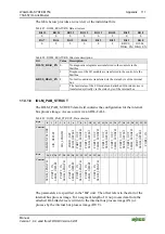
Страница 111: ... bus 11 3 1 6 IOLM_PAB_STRUCT The IOLM_PAB_STRUCT data field contains the configuration for the internal bus process image Access occurs via an IOL CALL Table 89 IOLM_PAB_STRUCT Data structure Byte 0 1 2 3 4 5 6 7 8 9 10 11 12 13 14 15 16 17 18 19 20 21 22 23 Content SEGMENT_MODE SIO_OFFSET SIO_LENGTH PORT1_OUT_ SEGM_OFFSET PORT1_ OUT _ SEGM_LENGTH PORT2_ OUT_ SEGM_OFFSET PORT2_ OUT_ SEGM_LENGTH P...

Страница 112: ...the data width available on the internal bus The control status byte and 2 bytes for the Mailbox are to be included The SEGMENT_MODE byte has the value 0x00 by default and the following structure Table 90 SEGMENT_MODE Data structure Bit 7 Bit 6 Bit 5 Bit 4 Bit 3 Bit 2 Bit 1 Bit 0 0 0 0 0 FRAG_ PORT4 FRAG_ PORT3 FRAG_ PORT2 FRAG_ PORT1 The following table describes the individual bits Table 91 SEGM...

Страница 113: ...er Access Factory Default Value Size Byte Active 0 PORT_CONFIG 1 0 r w r w Byte 1 0x00 Byte 0 0xC1 2 immediate 2 COMP_DATA 1 0 1 1 r w r w 0 24 immediate 26 MASTER_CMD 1 0 wo wo 0 1 immediate 27 PORT_INSPECTION_ LEVEL 1 0 r w r w 0 1 immediate 28 PARAM_SERV_MODI 1 1 r w r w 0 1 immediate 29 IOLD_FEATURE 1 0 r w r w 0 2 Start up 31 IOLD_RESERVED 1 0 r w r w 0 2 Start up The individual fields are de...

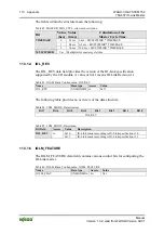
Страница 114: ...ink 4 Port mode COM1 IO Link 5 Port mode COM2 IO Link ro 6 Port mode COM3 IO Link PORT_OPERATION_MODE 7 15 Reserved 0 Free default 1 Synchronous not supported 2 Fixed value PORT_CYCLE_MODE ro 3 Reserved 0 2 Reserved PORT_PHYSICS ro 3 IO Link PHY 2 default PORT_CYCLE_TIME r w Var This is the required value for the cycle time on an IO Link port With a value of 0x00 the minimum cycle type of the atta...

Страница 115: ...ntation By default the field has the value 0x00 Table 98 MASTER_CMD Description Data field Data type Access Description MASTER_CMD UNSIGNED8 wo Master Command for the attached IO Link device 11 3 2 4 PORT_INSPECTION_LEVEL The Inspection Level indicates which parameters of an attached IO Link device have to match those of the current port configuration to be recognized as valid and if necessary a p...

Страница 116: ... not sent to the IO Link device by the I O module Application parameter upload The IOL D parameters are uploaded to the parameter server of the IO Link master if the device parameters have been changed This occurs either remotely via the bus or locally on the device In this case an internal flag is set in the device that is queried by the master when starting next Application parameter download Wh...

Страница 117: ..._FEATURE Description Bit Access Value Description 0 IO Link diagnosis IOL events disabled No diagnostic messages IOL events are transferred via the Mailbox to the control from the IO Link device attached to the port IOLD_DIAG_EN r w 1 IO Link diagnosis IOL events enabled Incoming diagnoses IOL events are sent via the Mailbox to the control from the IO Link device attached to the port 11 3 2 7 IOLD...

Страница 118: ...ial Number STRING 16 Serial number of the I O module Hardware Revision UNSIGNED16 Hardware version number Software Revision UNSIGNED8 4 See the following section Software version number Revision Counter UNSIGNED16 0 Not used Profile ID UNSIGNED16 4E00hex IO Link Profile Specific Type UNSIGNED16 0005hex Interface Module I M Version UNSIGNED8 2 01 hex 01hex v1 1 I M version I M supported UNSIGNED16 ...

Страница 119: ...ber of the IO Link master 005E871Chex Table 107 I M0 record field Serial Number Byte 0 1 2 3 4 5 6 7 8 9 10 11 12 13 14 15 Content 0x30 0x30 0x35 0x45 0x38 0x37 0x31 0x43 0x20 0x20 0x20 0x20 0x20 0x20 0x20 0x20 ASCII 0 0 5 E 8 7 1 C 11 3 3 3 Hardware Revision The Hardware Revision provides the revision number of the hardware as an UNSIGNED16 value Example hardware revision 0001 Table 108 I M0 reco...

Страница 120: ...r specific I M0 to I M4 records Read and write access are both possible By default the records are populated with 0x20 space 11 3 4 1 I M1 Table 110 I M1 Data structure Byte Name Data type Access 0 31 TAG_FUNCTION UNSIGNED8 32 r w 32 53 TAG_FUNCTION UNSIGNED8 22 r w 11 3 4 2 I M2 Table 111 I M2 Data structure Byte Name Data type Access 0 15 INSTALLATION_DATE UNSIGNED8 16 r w 16 53 RESERVED UNSIGNE...

Страница 121: ...D Vendor ID UNSIGNED16 Vendor ID Device ID UNSIGNED24 Device ID Serial Number STRING 16 Serial Number Hardware Revision Hardware Revision PD Input UNSIGNED8 Length of the process input data PD Output UNSIGNED8 Length of the process output data 11 3 4 4 1 Revision ID Table 115 Revision ID Structure Bit 7 Bit 4 Bit 3 Bit 0 Major Revision Minor Revision 11 3 4 4 2 Index CAP 1 Table 116 Master Configu...

Страница 122: ... display features Number of Ports UNSIGNED8 ro Number of IO Link ports available REF Port Config UNSIGNED8 ro Index to port configuration REF IO Mapping UNSIGNED8 ro Index to I O mapping REF iPar Directory UNSIGNED8 ro Index to iPar director REF IOL M UNSIGNED8 ro Index to IOL M parameters Number of CAP UNSIGNED8 ro Number of client access points 11 3 5 1 IO Link Version Table 118 Master configura...

Страница 123: ... Mapping Table 123 Master configuration REF Port Config Name Access Value Description REF IO Mapping ro 0x00 Reference to the IO mapping REF IO Mapping not supported The REF IO Mapping entry is not supported by the IO Link master 11 3 5 7 REF iPar Directory Table 124 Master configuration REF iPar Directory Name Access Value Description REF iPar Directory ro 0x00 Reference to the iPar directory REF...

Страница 124: ...alid from FW HW Version 02 01 11 3 5 9 Number of CAP Table 126 Master configuration Number of CAP Name Access Value Description Number of CAP ro 0x01 Number of client access points Pos 98 Dokumentation allgemein Gliederungselemente Seitenwechsel 3 mod_1221108045078_0 doc 21810 1 ...

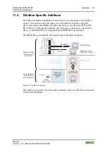
Страница 125: ...ation software and if necessary other device description files e g GSD GSE files for integration in a PROFIBUS environment The IODD file is provided by the manufacturer of the IO Link device 13 750 657 1 2 3 4 5 6 7 8 14 9 10 11 12 13 14 15 16 IO Link master GSD GSE files Configurator tool WAGO I O CHECK Manufacturer specific device description XML IO Link devices can only use a limited number of ...

Страница 126: ... Link master can be configured via PROFIBUS DP V1 An associated GSD GSE file is provided see the following section To exploit the PROFIBUS parameter assignment message most efficiently two variants with different parameterization range are provided P00 and P02 11 4 1 2 1 GSD GSE File The GSD GSE file contains the characteristics of the fieldbus coupler controller information about communication ca...

Страница 127: ...ytes Other GSD GSE entries 75x 657 IOL M SIO Mode PA P00 PA of the IO Link master 4 bytes 75x 657 IOL M 4 Byte PA P00 PA of the IO Link master 6 bytes 75x 657 IOL M 6 Byte PA P00 PA of the IO Link master 8 bytes etc The correct process image size appears when you read the I O module data using WAGO I O CHECK for example Figure 44 GSD GSE entries Observe the maximum number of I O modules Due to the...

Страница 128: ...fic diagnosis is enabled More information about the Mailbox is available in the section Mailbox 2 0 Transmission Method Further explanations about the subject of diagnoses is available in the section Diagnoses Parameter Port x Fragmentation If fragmentation for a port is ON the process data of the port is transmitted to the control and back in a fragmented manner via a Mailbox service 11 4 1 2 1 2...

Страница 129: ...er cycle time The adjustable number range reaches from 0 to 63 Parameter Port x Master cycle time The master cycle time is calculated as follows Table 127 PROFIBUS DP V1 calculation of the master cycle time Master cycle time Unit Multiplier 0 1 ms 6 4 multiplier 0 4 ms 32 0 multiplier 1 6 ms Parameter Port x Operating mode This parameter is used to set the operating mode of a port Table 128 PROFIB...

Страница 130: ... by a suitable function block in the PLC Parameter Port x Length of the output process image Table 129 PROFIBUS DP V1 parameter Port x Length of the output process image Name Value Data Type Lower limit Upper limit Def Portx Length of the output process image Var BitArea 0 15 0 This parameter is used to set the size of a port segment for the process output data on the internal bus in the unit Byte...

Страница 131: ...y of the acyclic channel the acyclic PROFIBUS DP V1 service is to be used in the PROFIBUS environment In addition Siemens has made an IOL_CALL function block available This block can be used to read or write different data areas accessible with the FI Index 98 see section Parameter Access Service IOL_CALL The input parameter CAP always used the value 255 Figure 47 IOL_CALL function block Siemens ...

Страница 132: ...ty_Number 1 Octet 0 63 IO Link port FI_Index 2 Octets 650xx IO Link profile specific Call Header IO Link specific extensions 236 Octets IO Link Extensions comprise an IO Link header with State IOL_Index and IOL_Subindex Body For access to the different data areas Table 131 Access to data areas Topic Index ExtFunc Entity FI Index IOL M Directory 255 0x08 0 65099 I M 0 255 0x08 0 65000 I M 1 4 255 0...

Страница 133: ...PROFIBUS DP Channel Diagnostics IOL event code Meaning Solution IOL type IOL mode Error code Error text 0x0000 No malfunction Alarm 0x1000 General malfunction Unknown error Error coming going 9 Error 0x1001 0x17FF Reserved 0x1800 0x18FF Manufacturer specific 0x1900 0x3FFF Reserved 0x4000 Temperature error Overload Error coming going 4 Overload 0x4001 0x420F Reserved 0x4210 Allowable device tempera...

Страница 134: ...ng going 3 Over voltage 0x5111 Allowable primary power supply not met Check the tolerance of the power supply Warning coming going 2 Over voltage 0x5112 Secondary power supply error Check the tolerance of the power supply Warning coming going 17 Warning 0x5113 0x5FFF Reserved 0x6000 Device software faulty Check the firmware version used Error coming going 9 Error 0x6001 0x630F Reserved 0x6310 Reco...

Страница 135: ...oing 9 Error 0x8C01 Simulation enabled Check the operating mode Warning coming going 0x8C02 0x8C0F Reserved 0x8C10 Process value exceeded Undefined process data Warning coming going 7 Process value exceeded 0x8C11 0x8C1F Reserved 0x8C20 Measuring Range Overflow Check the application Error coming going 7 Process value exceeded 0x8C21 0x8C2F Reserved 0x8C30 Process value not met Undefined process da...

Страница 136: ...values Check correctness Error coming going 9 Error 0x8CB3 The attached IOL device does not respond An attempt is made to communicate with the device again There may be a connection problem or error in the device 1 Check connection to the IOL device 2 Check IOL device for errors Warning once 0x8CB4 1 A short circuit on the respective port has been detected The short circuit may result from a defec...

Страница 137: ... data is greater than the maximum available memory size in the EEPROM Check data length Warning once 0x8CBE An error has occurred while uploading data to the parameter server Possible causes Checksum error during the ISDU transfer Other error in the ISDU telegram Warning once 0x8CBF An error has occurred while downloading data from the parameter server Possible causes Checksum error during the ISD...

Страница 138: ...oing 9 Error 0x8CC7 1 IOL device whose process data length is greater than the segmentation set is connected 2 Segmentation is set smaller than the process data length of the attached IOL device 3 The SIO byte and port specific segmentation have a length of 0 byte and the port is in the DI DO or SIO state Following solutions 1 Set segmentation to available process data length 2 Set segmentation to...

Страница 139: ...es 9 Byte Plus 20 Bytes 9 Byte Plus 24 Bytes 9 Byte Plus Coordinate segment limits of the process image and PDO limits As CAN telegrams are transferred in 8 byte segments make sure that the segment limits of the process image match the PDO limits when areas to be transferred 1 byte Possible delayed processing of adjacent segments can otherwise lead to data inconsistency 11 4 2 1 PDO Mapping The da...

Страница 140: ...140 Appendix WAGO I O SYSTEM 750 750 657 IO Link Master Manual Version 1 0 2 valid from FW HW Version 02 01 Figure 49 Receive PDO Mapping ...

Страница 141: ...ppendix 141 750 657 IO Link Master Manual Version 1 0 2 valid from FW HW Version 02 01 If the process image length is 4 bytes use an entry from the category 4 byte special see the following figure Figure 50 Send PDO Mapping ...

Страница 142: ...7 x 03 Channel quantity PDOUT 1 IDN S 0 1507 x 04 Channel width PDOUT 176 IDN S 0 1507 x 05 PDOUT Byte Designation Note 0 FC0 Acyclic channel register byte 0 1 MB0 Mailbox byte register byte 1 2 SIO SIO byte 3 D0 22 D19 Data bytes IDN S 0 1507 x 07 Channel quantity PDIN 1 IDN S 0 1507 x 08 Channel width PDIN 176 IDN S 0 1507 x 09 PDIN Byte Designation Note 0 FC0 Acyclic channel register byte 0 1 M...

Страница 143: ...Default Byte Designation Note 0 S0 Status byte 1 FC0 Acyclic channel register byte 0 2 MB0 Mailbox byte register byte 1 3 SIO SIO byte 4 D0 23 D19 Data bytes More information about sercos parameter model More information about the parameter model in sercos and about using the listed fieldbus parameters is available in the sercos specification v1 1 sercos International e V http www sercos org and i...

Страница 144: ...ss image size 48 Figure 20 Set options 49 Figure 21 Toolbar buttons 51 Figure 22 Display of Mailbox events 52 Figure 23 Display of diagnostic and error messages 53 Figure 24 Register Master Configuration 54 Figure 25 Register Port Configuration 58 Figure 26 IODD data of the respective ports 62 Figure 27 Register Module ID 64 Figure 28 Communication via Mailbox 2 0 75 Figure 29 Use of the handshake...

Страница 145: ...r Manual Version 1 0 2 valid from FW HW Version 02 01 Figure 48 Function block for DP V1 Write 132 Figure 49 Receive PDO Mapping 140 Figure 50 Send PDO Mapping 141 Pos 102 Dokumentation allgemein Gliederungselemente Seitenwechsel 3 mod_1221108045078_0 doc 21810 1 ...

Страница 146: ...olbar buttons 51 Table 21 Display of Mailbox events 52 Table 22 Display of diagnostic and error messages 53 Table 23 Register Master Configuration 55 Table 24 Register Master Configuration 56 Table 25 Internal bus process data Example of a segment distribution with a 2 byte Mailbox size 56 Table 26 Register PI Segmentation 56 Table 27 Register Port Configuration 59 Table 28 IODD interpreter button...

Страница 147: ...03 Table 68 Overview of I O module registers 104 Table 69 Control byte read register 08 105 Table 70 Status byte read register 08 105 Table 71 Register 33 possible values 106 Table 72 Master and port configuration 107 Table 73 Support tables for PROFIBUS 107 Table 74 IOL M Basic Configuration Access 108 Table 75 Data record IOL M Basic Configuration 108 Table 76 IOL M Basic Configuration NO_CHANNE...

Страница 148: ... Port Configuration Data 121 Table 115 Revision ID Structure 121 Table 116 Master Configuration Index CAP 1 121 Table 117 IOL M Directory Record 122 Table 118 Master configuration IO Link Version 122 Table 119 Master configuration IO Link Profile Version 122 Table 120 Master configuration IO Link Feature Support 122 Table 121 Master configuration Number of Ports 123 Table 122 Master configuration ...

Страница 149: ...YSTEM 750 149 750 657 IO Link Master Manual Version 1 0 2 valid from FW HW Version 02 01 Pos 105 Dokumentation allgemein Einband Einband Handbuch Leerseite für gerade Seitenzahl 3 mod_1219230851078_0 doc 21123 1 ...

Страница 150: ...eite 9 mod_1285229376516_21 doc 64944 1 WAGO Kontakttechnik GmbH Co KG Postfach 2880 D 32385 Minden Hansastraße 27 D 32423 Minden Phone 49 5 71 8 87 0 Fax 49 5 71 8 87 1 69 E Mail info wago com Internet http www wago com Ende der Liste für Textmarke Einband_hinten ...

Отзывы: