


WAGO-I/O-SYSTEM 750
I/O Modules 349
750-882 Media Redundancy ETHERNET Controller
Manual
1.5.0
13.2.4 Analog Output Modules
The hardware of an analog output module has 16 bits of measured analog data
per channel and 8 bits of control/status. However, the coupler/controller with
MODBUS/TCP does not have access to the 8 control/status bits. Therefore, the
coupler/controller with MODBUS/TCP can only access the 16 bits of analog data
per channel, which are grouped as words and mapped in Intel format in the
Output Process Image.
When digital output modules are also present in the node, the analog output data
is always mapped into the Output Process Image in front of the digital data.
Information on the structure of control and status bytes
For detailed information on the structure of a particular I/O module’s
control/status bytes, please refer to that module’s manual. Manuals for each
module can be found on the Internet at
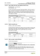
13.2.4.1 2 Channel Analog Output Modules
750-550, -552, -554, -556, -560, -562, 563, -585, (and all variations),
753-550, -552, -554, -556
Table 390: 2 Channel Analog Output Modules
Output Process Image
Offset
Byte Destination
Description
High Byte
Low Byte
0
D1
D0
Output Value Channel 1
1
D3
D2
Output Value Channel 2
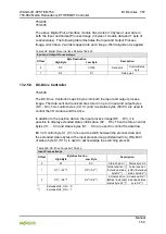
13.2.4.2 4 Channel Analog Output Modules
750-553, -555, -557, -559,
753-553, -555, -557, -559
Table 391: 4 Channel Analog Output Modules
Output Process Image
Offset
Byte Destination
Description
High Byte
Low Byte
0
D1
D0
Output Value Channel 1
1
D3
D2
Output Value Channel 2
2
D5
D4
Output Value Channel 3
3
D7
D6
Output Value Channel 4


