36 IO-Link Interface
787-1668/0000-0080 Electronic Circuit Breaker
Manual
Version 1.1.0, valid from firmware 2.4.0
7
IO-Link Interface
7.1
Cyclic Process Data
The IO-Link interface can be used to receive or transfer process data. The
individual input and output data are listed below in tabular form.
7.1.1
Output Data
Direction of communication:
Electronic circuit breaker
→
IO-Link Master
The output data is 5 bytes. Some of these bytes are configurable and can be
customized:
•
1st byte
: This byte contains collective messages that are transmitted for all
channels.
•
2nd byte:
This byte is used as a confirmation byte to identify what data is
transmitted to the master in this cycle via configurable bytes 3 ... 5.
•
3rd byte … 5th byte:
Configurable data. This data can be selected
separately via acyclic commands or cyclically as a contiguous dataset.
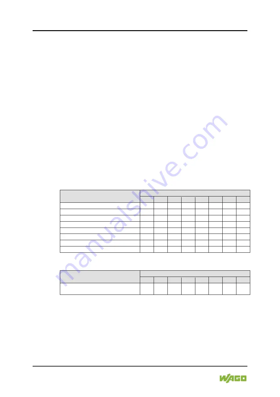
Table 19: Byte 1 – Collective Messages for All Channels
Description
Byte 1
Bit 7 Bit 6 Bit 5 Bit 4 Bit 3 Bit 2 Bit 1 Bit 0
Collective Message Off
0
0
0
0
0
0
0
1
Collective Message Tripped
0
0
0
0
0
0
1
0
Collective Message > 90 %
0
0
0
0
0
1
0
0
Collective Message > 100 %
0
0
0
0
1
0
0
0
Collective Message HW-FUSE
0
0
0
1
0
0
0
0
Collective Message Local Off
0
0
1
0
0
0
0
0
Input Voltage Alarm
0
1
0
0
0
0
0
0
Temperature Warning
1
0
0
0
0
0
0
0
Table 20: Byte 2 – Confirmation Byte for Data Transmission to the IO-Link Master
Description
Byte 2
Bit 7 Bit 6 Bit 5 Bit 4 Bit 3 Bit 2 Bit 1 Bit 0
Confirmation of the selection for bytes 3
… 5
1
0
0
0
0
0
0
0
0
1
The selection options are available in the Table “Possible Combinations for the Optional
Process Data Bytes”


