27
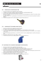
HERO 23D / Hero 23 / SF 23 Pro
2.3
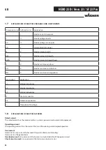
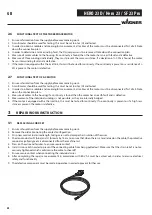
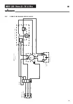
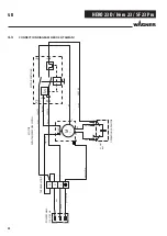
FUNCTIONAL TEST OF SWITCHES/BUTTONS
1. Ensure safe isolation from the supply before commencing work.
2. A multimeter or test buzzer should be used for testing. The function should be checked fi rst of all.
3. First disconnect all electrical connections at the switch or button.
4. With the switch in the 0 position, all of the switch connections must be checked against each other. If a continuity is found,
the switch is defective.
5 In position I of the switch the superimposed switch connections must have continuity. If no continuity is found, the switch is
defective.
6. The defective component must be made inoperative in order to prevent further use.
2.4
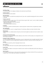
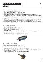
FUNCTIONAL TEST OF EARTHING CONTACT SOCKET
1. Ensure safe isolation from the supply before commencing work.
2. First perform a visual inspection of the socket for damage.
3 If no mechanical damage is found, work through chapter1.5 (The Five Safety Rules) in the reverse order.
4. A two-pole measuring instrument should be used to check the electrical functionality. If a multimeter is used, it should be
set to V~ or VAC.
5. Now check the voltage present between L1 and N. If this is 230 V AC then the voltage between L1 and PE must also be che-
cked.
6. If a deviation is found in point 2 or point 5, there is a defect.
7. The defective component must be made inoperative in order to prevent further use.
2.5
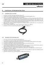
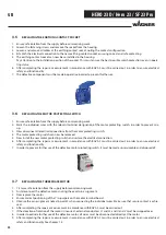
FUNCTIONAL TEST OF THE MOTOR OVERCURRENT PROTECTION SWITCH
1. Ensure safe isolation from the supply before commencing work.
2. First perform a visual inspection of the motor protection switch for damage.
3. A multimeter or test buzzer should be used for testing. The function should be checked fi rst of all.
4. Connect one test probe of the test buzzer to terminal N and the second one to terminal U1/Z1.
5. Now switch the motor overcurrent protection switch on and off two or three times. The buzzing tone sounds when the
switch is at one; no buzzing tone should be audible in the OFF position.
6. Now connect the test probes to terminals L1 and U2. Repeat point 5 as a check.
7. If a deviation is found in relation to point 5 or 2, there is a defect.
8. The defective component must be made inoperative in order to prevent further use.
GB

