background image

65

00

10

65

00

ADJUSTMENT

 Start on the transmitter. Inspect the value displayed and adjust the brass flat-head screw of 

the potentiometer on the circuit board. The potentiometer is a 20 turn device and has a 

self-protect mechanism. If you hear it click, you are at the limit and further turns will not 

affect the value. Clockwise (CW) increases the value and counter-clockwise (CCW) 

decreases the value. Adjust the transmitter potentiometer for a value of 2800. Once the TX 

value is 2800, no further adjustment of this potentiometer is required.

 Staying at the TX, inspect the value of the RC on the display. Remember anything over 4000 

is max limit. So if ever the receiver value displays 4000, turn the RC potentiometer CCW to 

2800.

 The three spring-loaded screws affect the beam angle. Remaining at the TX, adjust the 

screws CW one at a time to increase the RC displayed value to a maximum value. For 

example, adjusting screw A one turn will take the value from 1700 up to 2200 but any further 

turns on this screw will start to lower the RC value from 2200 back to 2000. So in this case, 

adjust screw A back to 2200. Then proceed to screw B. Adjusting screw B takes the value 

from 2200 up to 2350 but then starts to decrease again. Adjust screw B back to 2350. 

Repeat this process on the transmitter for all screws to obtain receiver maximum value. 

 Now proceed to the receiver. Repeat this procedure on the 3 spring-loaded screws on the 

RC. If at anytime the RC value goes above 4000, turn the RC potentiometer CCW to 2800.

Lastly, after all the 6 spring-loaded springs have been adjusted for a maximum value on the 

receiver display, adjust the receiver potentiometer for a value of 2800.

Turn the meter off and go into the diagnostic mode and verify the values of the TX and RC 

are approximately equal and then re-install the protective covers.


.


Содержание 6500

Страница 1: ...9 6375 Email info wagerusa com Homepage http www wagerusa com USA 1 800 562 7024 CANADA 1 800 655 5585 Telephone 336 969 6909 Robert H Wager Co Inc 570 Montroyal Road Rural Hall NC 27045 Rack Mount In...

Страница 2: ...ts Continued Technical Specifications Initial Installation Optical Beam Alignment Procedure Diagnostic Values Adjustment Follow Mode Test APPENDIX A MAINTENANCE APPENDIX B TROUBLE SHOOTING APPENDIX C...

Страница 3: ...r to unauthorized repairs or alterations Equipment components and accessories made by other manufacturers are warranted only to the extent of the original manufacturer s warranties to Seller The foreg...

Страница 4: ...a chart recorder The meter s simple design and rack mount makes it easy to access and obtain accurate measurements It provides an accurate means 1 of detecting and measuring the opacity of smoke emit...

Страница 5: ...eiver with Air and Water Chamber Transmitter with Air and Water Chamber Neutral Density Filter 2ND Fuse 2A 250VAC 5X20MM Fuse Holder Instruction Manual 194 0003 RACK 194 0004R 192 0015 194 0043 194 00...

Страница 6: ...ol unit is operated by a membrane keypad which consists of eight tactile feedback push buttons The display is an alphanumeric LCD containing 16 characters by two rows In low light situations the displ...

Страница 7: ...high temperatures for long durations Standard length is 50 feet Additional lengths are available upon request Power SUPPLY The meter is shipped with an AC Adapter Charger which operates under 110V or...

Страница 8: ...te life expectancy Check filter provided for easy calibration All solid state electronics Manufactured by an ISO 9002 company Applications The Model 6500 Smoke Meter can be used on any diesel engine w...

Страница 9: ...t going pipes In some high temperature applications a earth tone temperature insulator ceramic block maybe be installed between the water and air chambers Two adjustable clips are used to attach the o...

Страница 10: ...ith 3 screws and also will see 3 larger screws that mount the lens tube in the optic housing The lens tube is spring loaded with the 3 larger screws and acts as a tripod Adjusting these larger screws...

Страница 11: ...zes the automatic gain control and is required to stabilize the digital values Upon completion of this button series the LCD will show three values If you do not have 3 values turn the meter off and s...

Страница 12: ...s CW one at a time to increase the RC displayed value to a maximum value For example adjusting screw A one turn will take the value from 1700 up to 2200 but any further turns on this screw will start...

Страница 13: ...you see CALIBRATION COMPLETED it is too late to alter the mode and the unit should be powered off and then back on to gain access to the point where the mode can be changed Press the ON OFF button on...

Страница 14: ...ata can be printed in real time by keeping the optional Linseis Recorder attached while the test is performed Analog Output The WAGER Model 6500 Smoke Meter outputs a 0 1 V signal through the banana j...

Страница 15: ...d rub gently over lenses In laboratory settings and heavy commercial use please note that we have provided connectors for an external air purge Connecting Cables Connecting cables are subject to wear...

Страница 16: ...gives you a density of 64 57 To obtain the opacity reading subtract 64 57 from 100 total blockage of light for an opacity reading of 35 43 When you use this filter to check your unit a reading between...

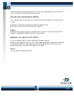
Страница 17: ...t is detected receiver This could be caused by several factors The sensor head assembly cable is not connected to the control unit The light source in the sensor head assembly has failed The connectin...

Страница 18: ...ction in the sensor head assembly or cable Action Clean the lenses as described in Maintenance section If this does not correct the problem call WAGER Technical Services for assistance MEMORY FULL DEL...

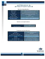
Страница 19: ...Liquid Crystal Display LCD 1 0 Nominal 10th digit No Drift 0 1 Volt or 0 1 MA 120 VAC 22 Watts in 18 VDC 800 MA out Size 16 3 4 W x 6 1 2 D x 4 1 2 H Rack Dimensions Range Warm up Time Response Time D...

Страница 20: ...from a source that is prevented from reaching a light detector Preliminary Snap Acceleration Test A series of Snaps usually at least 3 performed before testing begins to clear the exhaust system of r...

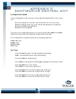
Страница 21: ...2 seconds The Configuration display will give you the following selections START TEST exit SELECT next ZERO change SAVE store Set Time Press the SELECT button The LED displays the following ZERO set t...

Страница 22: ...ct day 1 s digit Press SELECT to set year 10 s digit 06 12 98 Press ZERO to scroll to your correct year 10 s digit Press SELECT to set year 1 s digit 06 12 98 Press ZERO to scroll to your correct year...

Отзывы: