


RD 12/RD 16
Spray System
wc_tx000670gb.fm
67
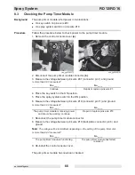
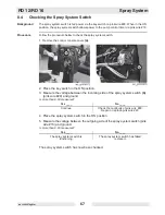
8.4
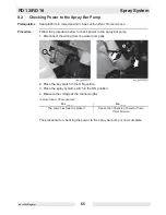
Checking the Spray System Switch
Background
The spray system switch is fed power via the key switch on pink wire #29. When in the ON
position, the spray system switch allows power to the pump control timer via pink wire #18.
Procedure
Follow the procedure below to check the spray system switch.
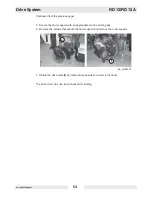
1. Remove the control console cover
(a)
.
2. Place the key switch in the ON position.
3. Measure the voltage between the incoming side of the spray system switch
(b)
(pink wire #29) and ground.
Is more than 9.8V measured?
4. Place the spray system switch in the ON position.
5. Measure the voltage between the outgoing side of the spray system switch (pink
wire #18) and ground.
Is more than 9.8V measured?
The spray system switch has now been checked.
Yes ____
No ____
Continue
Check the continuity of pink wire #29.
Repair or replace pink wire #29.
Yes ____
No ____
The spray system switch is
functioning.
The spray system switch has failed;
replace it.
Содержание RD 12A
Страница 1: ...5000192242 02 0912 5 0 0 0 1 9 2 2 4 2 Repair Manual Roller RD 12 EN...
Страница 15: ...RD 12 RD 12A Safety Information wc_si000302gb fm 15 1 4 Label Locations X FF...
Страница 21: ...RD 12 RD 12A Safety Information wc_si000302gb fm 21 Notes...
Страница 25: ...RD 12 RD 12A Operation wc_tx000865gb fm 25 53 47 54 61 50 62 55 wc_gr004114 56...
Страница 29: ...RD 12 RD 12A Operation wc_tx000865gb fm 29 wc_gr002951 N F R 55 42 44 54 10 15...
Страница 119: ...RD 12 RD 12A Disassembly Assembly wc_tx000671gb fm 119...
Страница 120: ...Schematics RD 12 RD 12A wc_tx001073gb fm 120 10 Schematics 10 1 Hydraulic Schematic...
Страница 122: ...Schematics RD 12 RD 12A wc_tx001073gb fm 122 10 4 Electrical Schematic A RD 12A...
Страница 124: ...Schematics RD 12 RD 12A wc_tx001073gb fm 124 10 6 Electrical Schematic B RD 12A...
Страница 126: ...Schematics RD 12 RD 12A wc_tx001073gb fm 126 10 8 Electrical Schematic RD 12...
Страница 137: ......