background image

RD 12 / RD 12A

Vibration System and Steering

wc_tx000668gb.fm

59

Continued from the previous page.

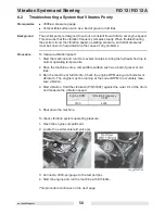
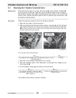
5. Turn on the vibration and measure the relief and operating pressures. The relief 

pressure is the pressure registered on the gauge as soon as the vibration is 

turned on. The system will then settle into operating pressure. Record these two 

pressures.

6. Shut down the machine.

Compare the results from operating pressure, pump relief pressure, and exciter 
speed with the chart below. 

N = Normal, L = Low, H = High

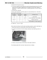
If the exciter is binding or causing high operating pressures, perform the following:

1. Disconnect and remove the exciter motor 

(c)

 from the housing.

2. Turn the motor shaft and exciter shaft by hand and check that they both turn 

freely.

3. If either component does not turn freely, it has failed; replace it.

The vibration system has now been checked for poor vibration.

Operating

Pressure

Pump Relief

Pressure

Exciter 

Speed

Probable Cause

N

N

N

System OK

H

N

N or L

Exciter bearings or motor binding

N or L

N

L

Exciter motor worn

L

L

L

Exciter pump damaged or worn, relief 

valve defective, or needs adjusting

wc_gr004143

c

Содержание RD 12A

Страница 1: ...5000192242 02 0912 5 0 0 0 1 9 2 2 4 2 Repair Manual Roller RD 12 EN...

Страница 2: ...distribution not authorized by Wacker Neuson Production Americas LLC represents an infringement of valid copyrights Violators will be prosecuted Trademarks All trademarks referenced in this manual are...

Страница 3: ...n to order a replacement Damage caused by misuse or neglect of the unit should be brought to the attention of the operator to prevent similar occurrences from happening in the future This manual provi...

Страница 4: ...2009 by Wacker Neuson Corporation No part of this publication may be reproduced in any form or by any means electronic or mechanical including photocopying without express written permission from Wack...

Страница 5: ...iliary Battery Positive Terminal 31 3 Honda Engine Starting System 32 3 1 Checking the 20A Main Fuse 33 3 2 Checking Wiring to the Starter Solenoid Anti backfire Solenoid 34 3 3 Checking the Key Switc...

Страница 6: ...ecking the Vibration Solenoid Valve 60 6 4 Checking the Vibration Switch 61 7 Steering System 62 7 1 Checking the Steering System Hydraulic Pressure 62 7 2 Troubleshooting the Steering System 63 8 Spr...

Страница 7: ...Control Lever 99 9 23 Removing the Exciter Pump 100 9 24 Installing the Exciter Pump 101 9 25 Removing the Drive Pump 102 9 26 Installing the Drive Pump 103 9 27 Removing the Engine 104 9 28 Installi...

Страница 8: ..._br0170797en_002TOC fm 8 11 Technical Data 128 11 1 Engine 128 11 2 Roller 129 11 3 Lubrication 129 11 4 Dimensions 130 11 5 Sound Measurements 131 11 6 Measurements of Operator Exposure to Vibration...

Страница 9: ...that follow this symbol to avoid possible injury or death DANGER indicates a hazardous situation which if not avoided will result in death or serious injury WARNING indicates a hazardous situation whi...

Страница 10: ...DO NOT attempt to start the machine when standing alongside it Only start the engine when seated in the driver s seat and with the forward reverse control in the neutral position 1 1 3 Do not allow an...

Страница 11: ...to support the weight of the machine with operator and that there is no danger of the roller sliding falling or tipping 1 1 16 ALWAYS wear protective clothing appropriate to the job site when operati...

Страница 12: ...refueling the engine 1 2 6 Do not run the engine near open flames 1 2 7 Do not run the machine indoors or in an enclosed area such as a deep trench unless adequate ventilation through such items as e...

Страница 13: ...gasoline is present A stray spark could ignite the fumes 1 3 6 Do not use gasoline or other types of fuels or flammable solvents to clean parts especially in enclosed areas Fumes from fuels and solve...

Страница 14: ...lings chains hooks ramps jacks and other types of lifting devices are attached securely and have enough weight bearing capacity to lift or hold the machine safely Always remain aware of the location o...

Страница 15: ...RD 12 RD 12A Safety Information wc_si000302gb fm 15 1 4 Label Locations X FF...

Страница 16: ...rating the machine Failure to do so increases the risk of injury to yourself or others B DANGER Engines emit carbon monoxide operate only in well ventilated area Read the Operator s Manual No sparks f...

Страница 17: ...0 130 in lbs maximum J CAUTION Lifting point K WARNING To prevent hearing loss wear hearing protection when operating this machine M WARNING Disconnect battery before servicing Read Repair Manual for...

Страница 18: ...and lubricate every 100 hours of operation V WARNING Avoid crushing area Articulated steering joint locking location Lock the articulated steering joint before servicing the machine Read Repair Manual...

Страница 19: ...or requesting service information you will always be asked to specify the model number item number revision number and serial number of the unit Z No lift point CC CAUTION Electric shock hazard at aux...

Страница 20: ...Safety Information RD 12 RD 12A wc_si000302gb fm 20 FF This machine may be covered by one or more patents Ref Label Meaning...

Страница 21: ...RD 12 RD 12A Safety Information wc_si000302gb fm 21 Notes...

Страница 22: ...ring cylinder under floor panel 10 Vibration control button 33 Tiedown 2 places 11 Exciter motor 34 Beacon light optional 12 Exciter Steering pump 35 Battery under floor panel 13 Hydraulic filter retu...

Страница 23: ...12 RD 12A Operation wc_tx000865gb fm 23 wc_gr002946 20 5 13 1 21 25 2 23 24 42 32 35 4 8 6 19 44 37 12 43 37 11 18 41 33 29 9 3 31 34 10 15 3 39 40 17 22 28 36 28 30 38 7 16 28 7 27 30 26 33 38 28 14...

Страница 24: ...See Graphic wc_gr004114 Ref Description Ref Description 47 Hour meter 55 Ignition switch 50 Vibration ON indicator 56 Low fuel indicator 53 Lights switch ON and OFF if equipped 61 Water spray switch O...

Страница 25: ...RD 12 RD 12A Operation wc_tx000865gb fm 25 53 47 54 61 50 62 55 wc_gr004114 56...

Страница 26: ...6 select either the front drum vibration or dual drum vibration by pressing the vibration switch 63 on the control panel CAUTION If the machine has been turned off with the vibration on the vibration...

Страница 27: ...o decrease the spray frequency Press the lower half of the water spray switch 61 to turn the water pump off Only use clean water Dirty water even when filtered will rapidly clog the tubes of the spray...

Страница 28: ...urn the ignition switch 55 to start the engine If the vibration indicator light 50 is on turn the vibration off by pressing the vibration control button 10 NOTICE Do not crank the engine starter for m...

Страница 29: ...RD 12 RD 12A Operation wc_tx000865gb fm 29 wc_gr002951 N F R 55 42 44 54 10 15...

Страница 30: ...ttle switch 54 and allow the engine to cool down 2 6 6 Set the parking brake 42 To set the parking brake pull the brake lever up until the brake pad engages the drum To release the brake lower the bra...

Страница 31: ...is machine is equipped with an auxiliary battery positive terminal 45 located on top of the hydraulic tank RD 12 or above the battery disconnect stud RD 16 CAUTION Electric shock hazard Never touch th...

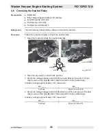
Страница 32: ...ttery and the cable connections to the battery The battery must be fully charged approximately 12V Sequence Complete the troubleshooting in the following sequence 1 Check the 20A main fuse 2 Check the...

Страница 33: ...Optional light circuit Procedure Follow the procedure below to check the 20A main fuse 1 Open the hood and locate the fuse carrier a 2 Remove the protective cover from the fuse carrier 3 Check the co...

Страница 34: ...r START positions If this wire is broken or disconnected the engine will not start Procedure Follow the procedure below to check the wiring to the starter solenoid and to the anti backfire solenoid 1...

Страница 35: ...e previous page 4 If the engine still won t start but cranks remove the anti backfire solenoid c and clean the valve portion of it with carburetor cleaner Re install it and try to start the engine The...

Страница 36: ...multimeter check the voltage between the BAT terminal b of the key switch and ground For easier measuring remove the plug and measure voltage at the plug Is battery voltage approximately 12V measured...

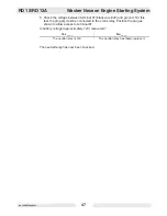
Страница 37: ...battery voltage approximately 12V measured 3 With the key switch in the START position check the voltage between terminal 86 black wire 04 and ground This test may be done at the plug b with it dis c...

Страница 38: ...osition 3 With the key switch in the START position check the continuity between the pins of the connector green and white wires Is there continuity 4 Place the control lever in the FORWARD or REVERSE...

Страница 39: ...ug b with it disconnected from the neutral relay Is battery voltage approximately 12V measured 4 Check the voltage between terminal 86 black wire 31 and ground This test may be done at plug b with it...

Страница 40: ...k the battery and the cable connections to the battery The battery must be fully charged approximately 12V Sequence Complete the troubleshooting in the following sequence 1 Check the 20A main fuse 2 C...

Страница 41: ...onal light circuit Procedure Follow the procedure below to check the 20A main fuse 1 Open the hood and locate the fuse carrier a 2 Remove the protectctive cover from the fuse carrier 3 Check the condi...

Страница 42: ...the hood and locate the starter starter solenoid a 2 Check the condition connection of black wire 20 b to the starter solenoid Is the wiring OK 3 Check the condition and connection of the black yellow...

Страница 43: ...the multimeter check the voltage between the BAT terminal b of the key switch and ground For easier measuring remove the plug and measure voltage at the plug Is battery voltage approximately 12V measu...

Страница 44: ...approximately 12V measured 3 With the key switch in the START position check the voltage between terminal 86 black wire 04 and ground This test may be done at the plug b with it dis connected from the...

Страница 45: ...AL position 3 With the key switch in the START position check the continuity between the pins of the connector green and white wires Is there continuity 4 Place the control lever in the FORWARD or REV...

Страница 46: ...hood and locate the neutral relay a 2 Place the key switch in the START position 3 Check the voltage between terminal 30 red wire 39 and ground This test may be done at the plug b with it disconnected...

Страница 47: ...black wire 20 and ground For this test the plug b must be connected to the crank relay Position the plug as shown to allow access to terminal 87 Is battery voltage approximately 12V measured The neutr...

Страница 48: ...when open allows oil flow to bypass the drive motors Drive Motors There are two drive motors one mounted to each drum The drive motors are plumbed in series System filters and strainers The hydraulic...

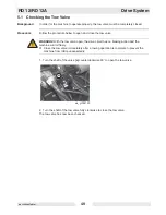
Страница 49: ...ow valve 1 Turn the shaft of the valve a counterclockwise 90 to open the tow valve 2 Turn the shaft of the tow valve fully clockwise to close the tow valve The tow valve has now been checked WARNING W...

Страница 50: ...n a hard level surface Engine running Forward reverse control in the NEUTRAL position Procedure Follow the procedure below to adjust the drive control cable 1 Loosen the lock nut b 2 Move the turnbuck...

Страница 51: ...Procedure Follow the procedure below to test the drive system operating pressure 1 Install a 3000 psi gauge in the forward test port a on the drive pump 2 Start the engine and run the machine at full...

Страница 52: ...Install a 5000 psi gauge in the forward test port a on the drive pump 4 Start the engine and run the machine at full throttle 5 Shift the forward reverse control slowly into forward until pressure on...

Страница 53: ...quisites Machine stopped Parking brake ON Battery disconnected Jacks Procedure To check for binding in the drive motor 1 Remove the drive motor cover a 2 Remove the drum support cover b 3 Support the...

Страница 54: ...5 Secure the drum support with an appropriate crane and sling e 6 Remove the screws that secure the drum support and remove the drum support 7 Rotate the drive plate f by hand and make sure the motor...

Страница 55: ...engine running and the drums rotating slowly apply the parking brake to the rear drum Observe the speed of both drums as the brake is applied Both drums should slow down at the same rate Apply the bra...

Страница 56: ...ross the exciter control valve limits pressure to 200 bar 2900 psi Steering circuit Steering is controlled by a steering valve and cylinder The steering wheel is spline mounted directly to the steerin...

Страница 57: ...to check the engine rpm and drum vpm 1 Start the engine and place the throttle switch in the FAST position 2 Measure the engine rpm using a vibrotach 3 Measure the vpm vibrations per minute by placing...

Страница 58: ...run it for several minutes to bring the hydraulic fluid up to normal operating temperature 2 Drive the machine onto a compactible surface such as a bed of gravel or old tires 3 Run the machine at full...

Страница 59: ...ith the chart below N Normal L Low H High If the exciter is binding or causing high operating pressures perform the following 1 Disconnect and remove the exciter motor c from the housing 2 Turn the mo...

Страница 60: ...y of the vibration solenoid a turn the vibration switch ON and feel for movement of the plunger inside the vibration solenoid Note If the movement of the plunger is hard to detect remove the solenoid...

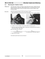
Страница 61: ...bration switch should be tested Procedure Follow the procedure below to check the vibration switch 1 Remove the four screws that secure the seat platform Then raise the platform 2 Locate the connector...

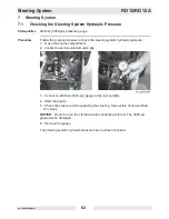
Страница 62: ...em hydraulic pressure 1 Open the engine compartment 2 Locate the exciter solenoid valve a 3 Connect a 200 bar 3000 psi gauge to the test port b 4 Start the engine 5 Check the pressure while operating...

Страница 63: ...vibration circuit This is due to the much lower pressure requirements of the steering circuit Procedure Follow the procedure below to check the steering system 1 Remove the steering valve from the mac...

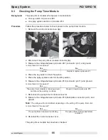
Страница 64: ...hoot the spray system If the machine does not start see engine starting troubleshooting Components The electrical components of the spray system consist of Pump Pump timer module Spray system switch S...

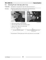
Страница 65: ...k power to the spray bar pump 1 Disconnect the wiring from the water pump a 2 Place the key switch in the ON position 3 Place the spray system switch in the ON position 4 Measure the voltage at the co...

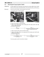
Страница 66: ...ray system switch in the ON position 6 Measure the voltage between pink wire 18 connector pin 11 and ground Is more than 9 8V measured 7 Reconnect the pump timer module connector 8 Measure the voltage...

Страница 67: ...e the key switch in the ON position 3 Measure the voltage between the incoming side of the spray system switch b pink wire 29 and ground Is more than 9 8V measured 4 Place the spray system switch in t...

Страница 68: ...el and serial number of the machine Parts Books are also available on the Wacker Neuson Corporation Web site See www wackerneuson com Enter the site as a visitor 9 3 Information Regarding Reference Nu...

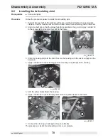
Страница 69: ...teering cylinder a from the pivot plate b 3 Remove the screws that secure each of the pillow blocks c to the frame 4 Rotate spread the machine halves as needed to better access to the articulating joi...

Страница 70: ...a so that the dowel hole b is parallel to the ground Apply Loctite 243 to the screws c and secure the shaft to the frame 3 Slide the housing d onto the shaft Secure the housing with the castle nut e a...

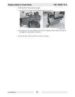
Страница 71: ...drum 2 Support the machine with jacks a 3 Remove the drum support covers b 4 Remove the bearing cover c from the non drive motor side of the drum 5 Disconnect and remove the brake cable d from the dr...

Страница 72: ...he previous page 7 Support the drum support with an appropriate sling and crane 8 Remove the four screws f that secure the drum support to the machine and slide the drum g from underneath the machine...

Страница 73: ...rear drum 1 Chock the front drum 2 Install the bearing h onto the shaft of the drum 3 Position the drum underneath the machine 4 Install the bearing cover c to the non drive motor side of the drum 5 A...

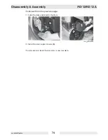
Страница 74: ...bly RD 12 RD 12A wc_tx000671gb fm 74 Continued from the previous page 7 Install the brake cable d to the drum 8 Install the drum support covers b The procedure to install the rear drum is now complete...

Страница 75: ...emove the drum support cover a 3 Remove the screws b that secure the brake lever assembly to the machine 4 Disconnect the brake cable c from the brake and the drum 5 Remove the brake lever and brake c...

Страница 76: ...crane 9 Remove the screws i that secure the drive plate to the shock mounts 10 Remove the screws h that secure the brake caliper to the drive plate 11 Raise the machine rear drum should remain on the...

Страница 77: ...n the nuts Slide the brake caliper around the drive plate then tighten the four screws i and nuts 3 Place the brake caliper into position so that when installed the two screws h will hold the brake ca...

Страница 78: ...secure the cable h to the machine 8 Install the hitch pin e and the clevis pin f 9 Run the cable through the drum support and connect it to the brake handle b 10 Secure the brake handle b to the machi...

Страница 79: ...is dif ficult to turn loosen the caps on the hydraulic lines leading to the motor to allow the release of any hydraulic pressure These are the caps connected to the lines while removing the drum 2 Usi...

Страница 80: ...6 Remove the motor guard g 7 Remove the brake bracket h 8 Remove the drive motor i from the drum support 9 Remove the hydraulic lines j and fittings from the drive motor if not already removed The pr...

Страница 81: ...to the drum support Torque the screws to 76 Nm 56 ft lbs 3 Install the brake bracket h 4 Install the motor guard g 5 Install the drive plate f to the hub g with the screws e Torque the screws to 44 Nm...

Страница 82: ...section Installing the Brake 8 Using an appropriate crane position the drum support drive motor assembly b on the drum Using Loctite 243 on the three screws a secure the drive motor assembly to the d...

Страница 83: ...t half of machine with jacks a 2 Remove the drum support covers b from each side of the machine 3 Remove the drive motor guard c 4 Remove the screws d that secure the drive plate to the drum 5 Disconn...

Страница 84: ...or from the machine 9 Disconnect and plug the hydraulic lines i from the exciter motor Then remove the exciter motor 10 Secure the drum support with an appropriate sling and crane 11 Remove the screws...

Страница 85: ...Loctite 243 to the screws a and secure the exciter motor side drum support to the frame Torque the screws to 79 Nm 58 ft lbs 3 Reconnect the hydraulic lines b to the exciter motor Apply Lotite 243 to...

Страница 86: ...que the nuts e to 76 Nm 56 ft lbs 6 Reconnect the hydraulic lines f to the drive motor 7 Apply Loctite 243 to screws g and secure the drive motor side drum support to the frame Torque the screws to 79...

Страница 87: ...the Front Drum 2 Remove the nut a that secures the hub b to the drive motor 3 Remove the screws c that secure the drive plate d to the hub 4 Slide the drive plate d off the hub 5 Pull the hub from th...

Страница 88: ...to the drum support b Torque the the screws to 76 Nm 56 ft lbs 2 Position the drive plate c and the hub d onto the shaft of the drive motor 3 Apply Loctite 243 to screws e and secure the drive plate...

Страница 89: ...Remove the screws a that secure the drum support b to the shock mounts and remove the drum support 2 Mark c the position of the motor mount d 3 Remove the motor mount d 4 Remove the shock mount plate...

Страница 90: ...Disassembly Assembly RD 12 RD 12A wc_tx000671gb fm 90 Continued from the previous page 7 Pull the exciter h up and out of the drum The procedure to remove the exciter is now complete wc_gr004164 h...

Страница 91: ...mporarily install the exciter side drum hub c onto the drum using three screws 4 Check the exciter for end play To do so grab the exciter b with a needle nosed pliers and pull and push it back and for...

Страница 92: ...ontinued from the previous page 5 Using Loctite 243 on the six screws e secure the bearing cover f and the shock mount plate g to the drum support Torque the screws to 50 Nm 36 ft lbs The procedure to...

Страница 93: ...gs and their flanges make up the drum hub d Follow the procedure below to disassemble the exciter bearings 1 Remove the retaining ring e 2 Use a puller to pull the smaller bearing flange f and bearing...

Страница 94: ...rive Motor 5 Remove the six screws a which secure the drive motor side bearing flange b and remove the bearing flange Note The drive motor side bearing flange is removed from inside the drum 6 Remove...

Страница 95: ...e the exciter bearings 1 Press new inner bearing races c2 and k2 onto the exciter 2 Install the outer bearing race into the drive motor side bearing flange b 3 Using Loctite 234 on the six screws a se...

Страница 96: ...ger bearing flange 5 Install a new outer seal i on the shaft of the larger bearing flange 6 Press the bearing h into the smaller bearing flange f 7 Press the two bearing flanges together to create the...

Страница 97: ...rive pump 2 Cut the wire ties b that secure the hoses wires and cables Maneuver the cable around the engine so that it is free up to the control lever 3 Disconnect the wiring at the connector c 4 Remo...

Страница 98: ...ge 5 Remove the screws e that secure the control lever assembly f and remove the con trol lever assembly from the machine 6 Disconnect the control cable a from the control lever assembly The procedure...

Страница 99: ...d with the screws g in the first and third holes of the control lever assembly f 2 Connect the control cable a to the control lever assembly f 3 Install control lever assembly f with the screws e 4 In...

Страница 100: ...al protection legislation 2 Disconnect and cap the outgoing hydraulic line a 3 Remove the two screws b that secure the exciter pump to the drive pump 4 Loosen the hose clamp c and pull the exciter mot...

Страница 101: ...machine to collect any liquid which drains off Dispose of this liquid in accordance with environmental protection legislation 2 Connect the hydraulic hose to the exciter pump with the hose clamp c 3 S...

Страница 102: ...ation 2 Disconnect the control cable a 3 Disconnect and the plug hydraulic lines b and c 4 Loosen the hose clamp from the hydraulic hose d 5 Remove the screws e that secure the hydraulic pump to the a...

Страница 103: ...ch drains off Dispose of this liquid in accordance with environmental protection legislation 2 Remove the plug from the hydraulic hose d and connect the hydraulic hose to the drive pump 3 Apply Loctit...

Страница 104: ...s a and the wiring b 2 Disconnect the exhaust c and the choke cable d 3 Cut the wire ties that secure the oil drain hose e 4 Disconnect the fuel line f This procedure continues on the next page Burn h...

Страница 105: ...ect and plug the exciter motor hydraulic line i from the hydraulic tank 8 Remove the screws that secure the hydraulic tank to the machine Position the tank j so that you can access the screws that sec...

Страница 106: ...engine into the frame 2 Reconnect the exhaust a 3 Apply Loctite 243 to the screws and secure the engine to the frame Torque the screws to 44 Nm 32 ft lbs 4 Disconnect the harness b and the wiring c 5...

Страница 107: ...g to the hydraulic tank 9 Reconnect the air cylinder h to the hydraulic tank 10 Reconnect the exciter motor hydraulic line i from the hydraulic tank 11 Secure the hydraulic tank to the machine Torque...

Страница 108: ...the front console panel a 2 Remove the cable clamp b 3 Remove the small cover c on the steering wheel 4 Remove the nut d that secures the steering wheel and remove the steering wheel 5 Remove the scre...

Страница 109: ...e previous page 7 Remove the screws g that secure the bracket h to the console 8 Remove the screws i that secure the steering servo Maneuver the steering valve j out of the control console The procedu...

Страница 110: ...below to install the steering valve 1 Position the steering valve j and bracket h into the control console Secure the steer ing valve to the bracket with screws i 2 Secure the bracket h to the console...

Страница 111: ...evious page 5 Install the steering wheel and secure it with the nut d 6 Install the small cover c on the steering wheel 7 Install the cable clamp b 8 Install the front console panel a The procedure to...

Страница 112: ...ose of this liquid in accordance with environmental protection legislation 2 Drain the hydraulic tank See section Changing Hydraulic Oil and Filter 3 Disconnect the lanyard g and the air cylinder h fr...

Страница 113: ...page 7 Loosen the hose clamps that secure the hydraulic hoses d and e to the drive and exciter pumps 8 Pull the hydraulic tank from the hydraulic hoses loosen the fittings if necessary and out of the...

Страница 114: ...ect any liquid which drains off Dispose of this liquid in accordance with environmental protection legislation 2 Connect the hydraulic hoses to the hydraulic tank and position the hydraulic tank into...

Страница 115: ...e previous page 5 Connect the lanyard g and the air cylinder h to the hydraulic tank 6 Connect the three hydraulic lines a 7 Fill the hydraulic tank See section Changing Hydraulic Oil and Filter The p...

Страница 116: ...Access Procedure Follow the procedure below to remove the fuel tank 1 Drain the fuel from the fuel tank by disconnecting the fuel hose a at the engine 2 Remove the screws b that secure the fuel spill...

Страница 117: ...the fuel sensor e from the wiring harness 6 Remove the gas strut brackets f from the water tank and the fuel tank Remove the cable clip g 7 Remove the mounting plate h from the water tank and the fuel...

Страница 118: ...ol lever side of the fuel tank Then position the fuel tank into the water tank and secure it with the mounting plate h Con nect the fuel level sensor to the harness 2 Install the gas strut brackets f...

Страница 119: ...RD 12 RD 12A Disassembly Assembly wc_tx000671gb fm 119...

Страница 120: ...Schematics RD 12 RD 12A wc_tx001073gb fm 120 10 Schematics 10 1 Hydraulic Schematic...

Страница 121: ...hine Ref Description Ref Description 1 Steering cylinder 8 Return filter 2 Steering unit 9 Tank 3 Drive motor 10 Suction strainer 4 Bypass lever 11 Vibration solenoid valve 5 Charge pump 12 Exciter mo...

Страница 122: ...Schematics RD 12 RD 12A wc_tx001073gb fm 122 10 4 Electrical Schematic A RD 12A...

Страница 123: ...ay 6 Low fuel indicator light amber 21 Neutral relay 7 Alternator 30A 22 Spray bar pump 8 Starter solenoid 23 Fuel cutoff solenoid 9 Starter motor 24 Reverse switch 10 Battery 25 Vibration switch 11 F...

Страница 124: ...Schematics RD 12 RD 12A wc_tx001073gb fm 124 10 6 Electrical Schematic B RD 12A...

Страница 125: ...indicator light amber 21 Neutral relay 7 Alternator 30A 22 Spray bar pump 8 Starter solenoid 23 Fuel cutoff solenoid 9 Starter motor 24 Reverse switch 10 Battery 25 Vibration switch 11 Fuel level sen...

Страница 126: ...Schematics RD 12 RD 12A wc_tx001073gb fm 126 10 8 Electrical Schematic RD 12...

Страница 127: ...t amber 22 Spray bar pump 7 Alternator 30A 23 Fuel cutoff solenoid 8 Starter solenoid 24 Reverse switch 9 Starter motor 25 Vibration switch 10 Battery 26 Neutral switch 11 Fuel level sensor 27 Seat sw...

Страница 128: ...rated power rated speed kW hp 13 4 18 0 3600 rpm 15 3 20 5 3600 rpm Displacement cm in 614 37 5 653 39 9 Spark plug NGK BPR6ES NGK BPR6ES high heat NGK BP6ES Electrode gap mm in 0 71 0 79 0 028 0 031...

Страница 129: ...ward Reverse Speed km hr mph 0 8 7 0 5 4 Gradeability 30 Vibration Frequency vpm 4200 Item No RD 12A RD 12 Lubrication Engine Lubrication type l pt SAE 10W30 Class SG SF or SE rated 1 6 3 5 Hydraulic...

Страница 130: ...Technical Data RD 12 RD 12A wc_td000311gb fm 130 11 4 Dimensions mm in 2300 90 6 560 22 1265 49 8 1824 71 8 900 35 4 1035 40 8...

Страница 131: ...isted below when using the machine in performance of its normally intended function Maximum hand arm vibration levels are RD 12 1 4 m s2 4 6 ft s2 These are the representative values of the weighted r...

Страница 132: ...rd packed surface shown Values may differ depending on surface Charge pressure 11 4 12 8 bar 165 185 psi System Operating Pressure Relief Pressure bar psi bar psi Drive 55 69 800 1000 200 2900 Steerin...

Страница 133: ...311 5 ml 17380 50 ml Loctite 271 277 Hernon 427 Omnifit 1550 220M Red High strength for all threads up to 25 mm 1 Heat parts before disassembly Temp range 54 to 149 C 65 to 300 F 29312 5 ml 26685 10 m...

Страница 134: ...follow instructions on container The sealants listed are recommended for use on Wacker Neuson equipment TYPE Europe COLOR USAGE PART NO SIZE Loctite 496 Hernon 110 Omnifit Sicomet 7000 Clear Instant a...

Страница 135: ...5 M4 2 9 26 4 1 36 4 9 43 7 9 32 3 M5 6 0 53 8 5 6 10 7 8 5 16 4 M6 10 7 14 10 17 13 10 5 M8 25 18 35 26 41 30 13 1 2 6 M10 49 36 69 51 83 61 17 11 16 8 M12 86 63 120 88 145 107 19 3 4 10 M14 135 99 1...

Страница 136: ...8 2 5 22 3 5 31 4 7 42 9 11 32 9 64 No 10 3 6 32 5 1 45 6 8 60 3 8 5 32 1 4 8 1 6 12 9 16 12 7 16 3 32 5 16 18 13 26 19 33 24 13 1 2 1 4 3 8 31 23 45 33 58 43 9 16 5 16 7 16 50 37 71 52 94 69 16 5 8...

Страница 137: ......
Страница 138: ...2 390 Wacker Neuson Corporation P O Box 9007 Menomonee Falls WI 53052 9007 Tel 262 255 0500 Fax 262 255 0550 Tel 800 770 0957 Wacker Neuson Limited Room 1701 03 1717 20 17 F Tower 1 Grand Century Plac...

Отзывы: