1
Introduction
2
WABCO
Maintenance Manual 31 (Revised 08-18)
Operation
The compressor is driven by the engine and its crankshaft turns
continuously while the engine is running. Compression of air is
controlled by the
governor
and by the
compressor’s unloading
mechanism
.
The
governor
maintains the brake system air pressure at preset
maximum and minimum levels. The governor is mounted apart from
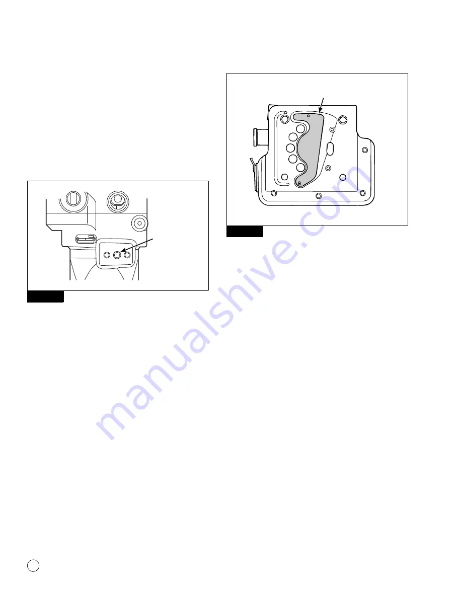
the compressor, either horizontally or vertically. The governor port is
located on the crankcase of the compressor. Figure 1.3.
Figure 1.3
The
unloader mechanism
controls the air compression cycle; an
air compression cycle has three phases:
1.
Induction:
Air flows from the engine to the compressor,
opening an inlet valve in the cylinder head of the compressor.
2.
Compression:
Air pressure is increased, causing the
compressor’s discharge valve to open.
3.
Unloading:
Air passes from the cylinder to the inlet chamber of
the cylinder head via a port controlled by a sliding leaf valve.
When system cut-in pressure is reached, air is exhausted from
the unloader port.
4.
After unloading, the unloader piston returns the sliding leaf
valve to the loaded position. This seals the unloader ports and
compression resumes. Figure 1.4.
Figure 1.4
Maintenance Intervals
The WABCO System Saver 318 air compressor receives inlet air, oil
and coolant from the engine, so it is important to follow the engine
manufacturer’s recommendations and maintenance schedules
regarding fluid levels, air filter and recommended change intervals.
Cylinder Head
Remove carbon deposits from the discharge cavity and rust and
scale from the cooling passages of the cylinder head.
Clean carbon and dirt from the inlet and unloader passages.
NOTE:
Shop air may be used to blow the carbon and dirt deposits
from the unloader passages.
Figure 1.3
GOVERNOR
PORT
1003374b
Figure 1.4
1003375b
SLIDING LEAF
VALVE
Содержание System Saver 318
Страница 4: ...Notes...


