background image

14

4

CAN Router
CAN Repeater

Workshop instructions

CAN router in 
combination with Trailer 
EBS

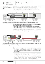
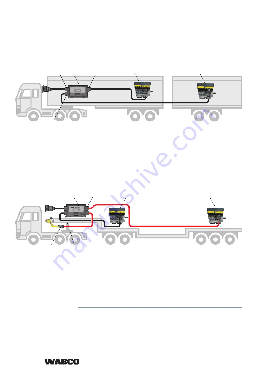
If the CAN router is used in Eurocombis or Roadtrains, make sure that the sequence
for connected T-EBS modulators is identical with the sequence of trailers.

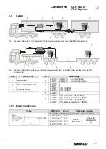
• Power OUT1 (X1): Connection of the 1st T-EBS modulator / 1st trailer (2.1)

• Power OUT2 (X2): Connection of the 2nd T-EBS modulator / 2nd trailer (2.2)

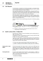
Fig.

Using the CAN router (1) in a "Eurocombi" tractor-trailer combination with two Trailer EBS modulators (2.1, 2.2)

The CAN signal that is generated by the external pressure sensor is only passed on
via the Power OUT1 (X1) connection of the CAN router:

• Power OUT1 (X1): Passing on the CAN signal from external pressure sensor

• Power OUT2 (X2): Not passing on the CAN signal from external pressure sensor

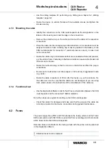
Therefore, when using the CAN router in a trailer with two T-EBS E1 modulators, the
rear modulator (2.1) is always to be connected to the Power OUT1 (X1) connection
of the CAN router (1) to achieve optimal timing.

Fig.

Using the CAN router (1) with external pressure sensor (3) in a Flat Bed Trailer with two Trailer EBS E1 modulators (2.1, 2.2)

4.1.2 Mounting the CAN Router / Repeater

!

Remove the POWER plug of the Trailer EBS modulator for welding work. Position 
the ground connection of the welder directly next to the welding location. Always 
position the ground connection for the welder directly in the vicinity of the welding 
location, to prevent magnetic fields and current flow via cables or components of 
the Trailer EBS.

– Disconnect the power supply to the towing vehicle. Consider any short-circuit

hazards from batteries in the towing vehicle.

– Position the device to be accessible on the vehicle frame so that changing a fuse

is possible. The installation location of the device should be parallel to the cable
route to prevent unnecessary bending radii in the connecting cable. The CAN
repeater should be mounted in the front or on the side of the trailer.

1

X2

X1

2.1

2.2

Z

1

X2

X1

2.2

2.1

3

1

Содержание CAN Router

Страница 1: ...t Edition This publication is not subject to change procedures New versions can be found in INFORM under www wabco auto com Copyright WABCO 2010 Vehicle Control Systems Changes are subject to change w...

Страница 2: ...ensor 441 044 101 0 102 0 10 3 5 Cable 11 3 5 1 Power supply cable 11 3 5 2 Sensor cable 12 4 Workshop instructions 13 4 1 Mounting and Installation 13 4 1 1 Installation concept 13 4 1 2 Mounting the...

Страница 3: ...regulations Wear suitable protective clothing when necessary Your workspace must be dry as well as sufficiently illuminated and ventilated Risk of injury Pedal actuations can lead to severe injuries...

Страница 4: ...connections when fastening the ECUs to the vehicle frame Use only cable conforming to WABCO specifications or WABCO original cable Run the cable in metallic casing if at all possible e g inside the U...

Страница 5: ...CAN brake signal of the towing vehicle is received by the CAN Router and distributed to the Trailer EBS modulators Fig Using a CAN router 1 in a Eurocombi tractor trailer combination with two Trailer...

Страница 6: ...outer repeater is used with the WABCO electronic braking system T EBS of generations E and D Using trailers with CAN routers repeaters is permitted on towing vehicles with CAN interfaces with at least...

Страница 7: ...acceptance that all respective requirements of the towing vehicle disconnected supply line to second trailer etc are met by the system When using the CAN router for vehicle combinations with more than...

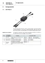
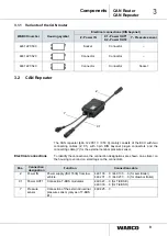
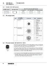
Страница 8: ...nnection designations are shown on a sticker on the housing cover and on small tags on the connectors Z X1 X2 Y Pos Connection designation Function Connection cable Z Power IN Power supply ISO 7638 fr...

Страница 9: ...small tags on the connectors WABCO number Housing symbol Electrical connections DIN bayonet Z Power IN X1 Power OUT1 X2 Power OUT2 Y Pressure sensor 446 122 050 0 Socket Connector 446 122 052 0 Connec...

Страница 10: ...nected to the IN OUT 2 connector of the T EBS modulator As of version 1 5 of the Trailer EBS E production date from CW 49 2009 in the diagnostic software Trailer EBS E with connected external pressure...

Страница 11: ...ailer 449 231 0 449 233 0 for drawbar trailer 2 Trailer EBS E Modulator 5 449 135 0 449 231 0 3 Pressure sensor 6 449 347 0 for T EBS E 449 333 0 for T EBS D 7 449 425 0 8 449 173 0 for semitrailers w...

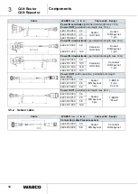
Страница 12: ...max 18 m 449 233 030 0 3 0 Connector ISO 7638 Connector DIN bayonet 7 pin 449 233 100 0 10 0 449 233 140 0 14 0 449 233 180 0 18 0 Power OUT1 with connection permitted total length max 80 m 449 347 00...

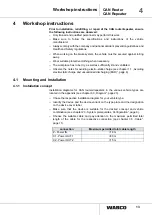
Страница 13: ...electro static charge see chapter 1 1 Avoiding electro static charge and uncontrolled discharging ESD page 4 4 1 Mounting and Installation 4 1 1 Installation concept Installation diagrams for CAN rou...

Страница 14: ...always to be connected to the Power OUT1 X1 connection of the CAN router 1 to achieve optimal timing Fig Using the CAN router 1 with external pressure sensor 3 in a Flat Bed Trailer with two Trailer...

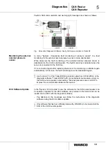
Страница 15: ...he cable and plug so that no tension or lateral forces affect the plug in connections Be sure not to route cables over sharp edges or in the vicinity of aggressive media e g acids Fasten the cable a m...

Страница 16: ...ermine the position of the defective fuse The position can be located in the diagnostic memory Mark the cover and the housing of the ECU if necessary so that the alignment is not wrong when the cover...

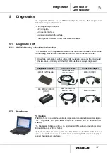
Страница 17: ...e CAN routers in sequence the CAN router that is connected directly with the ISO 7638 interface is always diagnosed 5 2 Hardware PC Laptop WABCO offers you a workshop suitable impact and contamination...

Страница 18: ...s There you will find further information and can order the Diagnostic Software in your language and to load onto your PC 5 3 1 Diagnostic Software Trailer CAN Router Repeater If a diagnostics connect...

Страница 19: ...the monitoring is activated again automatically In this case the fault monitoring must be deactivated again As of version 1 5 of the Trailer EBS E production date from CW 49 2009 in the diagnostic sof...

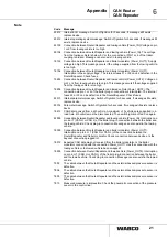
Страница 20: ...connection Power_IN 181 Power supply connection Power_OUT1 182 Power supply connection Power_OUT2 253 Parameter setting 254 Control unit 255 Internal operating software Code Message 0 Value too high 1...

Страница 21: ...f message still exists replace device 25314 Parameter message Switch off ignition for 5 seconds If message still exists replace device 18413 CAN data received from a 6th vehicle A maximum of 5 vehicle...

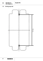
Страница 22: ...22 6 CAN Router CAN Repeater Appendix 6 2 Drilling template...

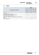
Страница 23: ...0 841 601 245 0 841 701 055 0 841 701 057 0 841 701 058 0 CAN Router X X X CAN repeater with pressure sensor X X X Select High for RSS in Eurocombi Roadtrain X X Select Low for trailing steering axle...

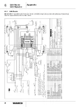
Страница 24: ...Router CAN Repeater Appendix 6 3 1 CAN Router 841 601 287 0 Trailer EBS E with CAN router 4S 2m or 2S 2M in dolly for Eurocombis or Roadtrains with Select High valve for improved RSS control in entire...

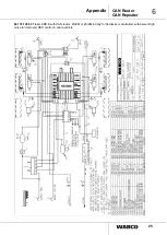
Страница 25: ...25 6 CAN Router CAN Repeater Appendix 841 701 228 0 Trailer EBS E with CAN router 4S 2M or 2S 2M in dolly for flatdecks semitrailers with Select High valve for improved RSS control in entire vehicle...

Страница 26: ...26 6 CAN Router CAN Repeater Appendix 841 601 245 0 Trailer EBS E with CAN router 2 x 2S 2M in a vehicle...

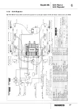
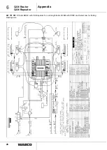
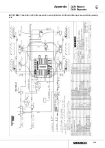
Страница 27: ...27 6 CAN Router CAN Repeater Appendix 6 3 2 CAN Repeater 841 701 055 0 Trailer EBS E with CAN repeater for overlength trailers 4S 3M with trailer release valve and PEM...

Страница 28: ...28 6 CAN Router CAN Repeater Appendix 841 701 057 0 Trailer EBS E with CAN repeater for overlength trailer 4S 3M with PREV and Select Low for trailing steering axle...

Страница 29: ...29 6 CAN Router CAN Repeater Appendix 841 701 058 0 Trailer EBS E with CAN repeater for overlength trailers 4S 3M with EBS relay valve and trailing steering axle...

Отзывы: