6.
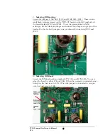
Selecting MC Load:
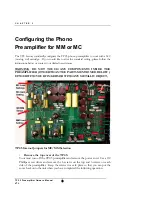
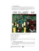
Locate the MC Load jumpers across the top edge of the PC board in the
locations labeled L MC LOAD and R MC LOAD. Note that there are five 2
pin headers, L1 to L5, to set the load option. Place the jumper across one of
the 5 sets of pins to select the appropriate Load option.
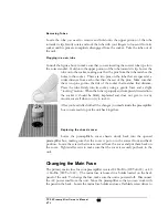
As noted in the photo above, the MC load options are as follows:
100 ohm – header across L1
250 ohm – header across L2
470 ohm – header across L3
1K – header across L4
5K – header across L5
47K – header off and not connected (you can put the header across one single pin
in both channels)
7.
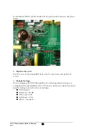
Enhanced and standard RIAA
Locate the Enhanced RIAA jumpers on the PC board in the locations R ENH
RIAA and L ENH RIAA. Place the jumper across both pins of this header to
select standard RIAA.
TP2.5 Preamplifier Owner’s Manual
VTL
11


