background image


The 

Status toggle

 switch is a 3-position toggle switch to allow you to switch the 

phono preamplifier between operating mode, the mute state and Rumble on state.  
When the toggle switch is in the middle position, the preamplifier is in its operating 
state.   Change the preamplifier to the mute state by pressing the switch down.  If 
the preamplifier is currently in mute state, press this switch up to change the 
system back into the operating state. 


When the status switch is in the up position, the 

Rumble

 feature is selected. 


The 

Status 

LED indicates whether the preamplifier is in operating state or in muted 

state.  When the LED light is on, the preamplifier is in operating state.  When the 
LED light is on and flashing, the preamplifier is in mute state.  The LED is off 
when the preamplifier is powered off. 


The 

Power On/Off

 switch can be used to turn the preamplifier on and off.  Press the 

switch up to turn the preamplifier ON and press the switch down to turn the unit 
OFF.  The 

Status 

LED should be on and off respectively, according to the setting 

of the 

Power On

 switch. 

The Preamplifier’s Back Panel 

From the Preamplifier’s back panel, you can access the input, output, ground and 
power connectors, the main fuse holder, the serial number, and the voltage setting of 
the unit.   


RISK OF ELECTRIC SKOCK

1A Slo Blo (120V)

4/10 A Slo Blo (240V)

AC POWER

TP2.5 Phono Preamplifier

For continious protection
against fire hazard replace only
with fuses of same type and rating.

To prevent electric shock DO NOT remove cover.
No user servicable parts inside. Refer servicing
to qualified personnel. To prevent fire or shock
do not expose this appliance to rain or moisture.

Manufactured by:

VTL Amplifiers Inc.
4774 Murrieta Street Suite 10
Chino, CA 91710 USA
(909) 627-5944

Output

Inputs

MM

MC

Left

Right

GND

AC INPUT

FUSE HOLDER

INFORMATION LABEL

OUTPUT RCA'S

MM INPUT RCA'S

MC INPUT RCA'S

GROUND CONNECTOR


Connecting Your Phono Preamplifier to your 
system 

1. 

Connect the turntable to the TP2.5 preamplifier.

  Make sure that the 

preamplifier and the turntable is powered off.  Connect the output cable from the 
turntable to either the 

MM

 or 

MC


Input

 connectors of the TP2.5 preamplifier, 

TP2.5 Preamplifier Owner’s Manual 
VTL 

5

Содержание TP2.5

Страница 1: ...VTL TP2 5 Phono Preamplifier Owner sManual ...

Страница 2: ...duced or transmitted in any form or by any means electronic or mechanical for any purpose without the express written permission by VTL Version History Version 2 0 September 21 2012 Part Number OM 0495 Copyright 2012 by VTL Amplifiers Inc All rights reserved 4774 Murrieta Street Suite 10 Chino CA 91710 USA Phone 909 627 5944 Fax 909 627 6988 email mail vtl com http www vtl com ...

Страница 3: ......

Страница 4: ...P 2 5 Front Panel Controls 4 The Preamplifier s Back Panel 5 Connecting Your Phono Preamplifier to your system 5 Powering the system off 7 CHAPTER 3 8 CONFIGURING THE PHONO PREAMPLIFIER FOR MM OR MC 8 CHAPTER 4 13 CARE AND MAINTENANCE OF YOUR VTL PREAMPLIFIER 13 BREAK IN PERIOD 13 Changing Tubes 13 Changing the Main Fuse 15 Cleaning 16 Troubleshooting 16 CHAPTER 5 18 SPECIFICATIONS 18 CHAPTER 6 19...

Страница 5: ......

Страница 6: ...the convenience and flexibility to manage your analog input while at the same time giving you the musical experience that is the most alive and the truest to your source and we hope you ll get many hours of enjoyment from it Symbol Conventions used in this guide Certain symbols are used in this owner s manual to draw your attention to important points being discussed For your own safety and that o...

Страница 7: ...use serious injury if they come in contact with you Location and Ventilation Warning Toavoidriskoffailureduetooverheating donotstackcomponents The TP 2 5 chassis emits heat and needs proper ventilation to ensure long operational life Under no circumstances should the TP 2 5 be stacked on top of or below any other unit Ensure that the TP 2 5 is installed in a location that is stable and well ventil...

Страница 8: ...unit and will not be covered under the warranty Ensure that no interconnect cables can become loose during use and that there are no intermittent faults or shorts with the cables Do not attempt to disassemble the TP 2 5 chassis or remove any covers from the unit Always consult with your VTL authorized dealer or the VTL factory before attempting any service work on any VTL unit Do not touch the tub...

Страница 9: ...he tubes appear properly seated firmly in their sockets Contact your VTL dealer immediately if physical damage is detected TP 2 5 Front Panel Controls You can operate the switches from the front panel to control the power on off mute and rumble functions The Status indication LED shows whether the unit is on or in mute The Status LED indicates the power on status of the preamplifier When the unit ...

Страница 10: ...nd off respectively according to the setting of the Power On switch The Preamplifier s Back Panel From the Preamplifier s back panel you can access the input output ground and power connectors the main fuse holder the serial number and the voltage setting of the unit RISK OF ELECTRIC SKOCK 1A Slo Blo 120V 4 10 A Slo Blo 240V AC POWER TP2 5 Phono Preamplifier For continious protection against fire ...

Страница 11: ...he left and right output channels from the TP2 5 phono preamplifier to the input connectors of your line stage preamplifier or integrated amplifier Make sure that the left and right output channels from the TP2 5 are connected to the left and right input channels of your line stage preamplifier If you are using the VTL TP2 5 preamplifier you can connect the outputs from the TP2 5 to the Phono Aux ...

Страница 12: ...l of the preamplifier and that the power cable is plugged into the AC supply Contact your VTL dealer if the unit still will not power up after these checks have been performed 5 Turn on the line stage preamplifier followed by the power amplifier Alternatively if you are using an integrated amplifier only turn on the integrated amplifier 6 Put on your favorite record and get ready for some good mus...

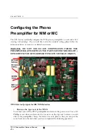
Страница 13: ...DE THE PREAMPLIFIER OTHER THAN THE PARTS MENTIONED BELOW EITHER WITH YOUR FINGERS OR WITH ANY METALLIC OBJECT TP2 5 Internal Jumpers for MC MM Selection 1 Remove the top cover of the TP2 5 Your must turn off the TP2 5 preamplifier and remove the power cord Use a 2 Phillips screw driver and remove the 6 screws on the top and 3 screws on each side of the preamplifier Keep the screws in a safe place ...

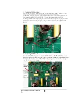
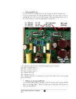
Страница 14: ... the black pin jumper and connect the jumper a single pin of the header Do this for both jumpers one per channel in locations JP101 and JP201 3 Selecting MM load Locate the MM load positions marked L TX SEL and R TX SEL You can select the Load for either 47K or 100K When the jumper is connected across both pins the load is set to 47K When the jumper is connected to one pin only the load is set to ...

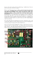
Страница 15: ...on the left hand side of the board marked JP101 and JP201 To set the preamplifier for MC cartridges connect the jumpers across both pins of the headers 5 Selecting MC Gain Locate the MC Gain jumpers L GAIN SEL and R GAIN SEL Place the header across either the 62 dB or 56 dB headers for each channel TP2 5 Preamplifier Owner s Manual VTL 10 ...

Страница 16: ...d in the photo above the MC load options are as follows 100 ohm header across L1 250 ohm header across L2 470 ohm header across L3 1K header across L4 5K header across L5 47K header off and not connected you can put the header across one single pin in both channels 7 Enhanced and standard RIAA Locate the Enhanced RIAA jumpers on the PC board in the locations R ENH RIAA and L ENH RIAA Place the jum...

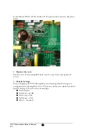
Страница 17: ...insert and tighten all screws 9 Default Settings Prior to shipping the TP2 5 Preamplifier the following default settings are configured in the preamplifier at the VTL factory unless your dealer has asked specific settings to match with your cartridge MC Selected MC Gain 62 dB MC Load 47K MM Load 47 K RIAA standard TP2 5 Preamplifier Owner s Manual VTL 12 ...

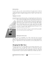
Страница 18: ...e new sound quality Your VTL dealer or VTL factory service department will be happy to assist you with the re tubing process Note use only tube types and tube brands that are recommended by VTL VTL specified replacement tubes are available from your authorized VTL dealer or the VTL factory service department Any damage incurred to units which use non VTL approved tubes will not be covered under th...

Страница 19: ...e to understand these constraints before going any further If at this stage you feel that you would rather not attempt this procedure yourself you can take the unit to your VTL Authorized Dealer to have the work done If you feel comfortable with undertaking the procedure yourself then be sure to only touch the tubes themselves and do not allow any part of your body or hanging jewelry to come into ...

Страница 20: ...ompletely inserted into the socket it should be firmly implanted and does not give in to any movement at all when you try to rock it After you re satisfied with all the changes you made inside the preamplifier box you are ready to put the unit back together Replacing the chassis cover Lower the preamplifier s cover chassis slowly back into the opened preamplifier box making sure that the cover is ...

Страница 21: ...th the power source check the fuse unit in the back panel of the preamplifier If the fuse is blown change the fuse Turn the power on the preamplifier again If the problem still persists contact your authorized VTL dealer immediately 3 I am getting a noise and hum coming from my system when I turn the system on What can I do to eliminate the noise It is recommended that you connect as many componen...

Страница 22: ...r more of the tubes in the preamplifier may be the source of the problem Follow the procedures listed in this manual to remove the tubes and change them for new ones TP2 5 Preamplifier Owner s Manual VTL 17 ...

Страница 23: ... Maximum Output Voltage 20 Volts Gain 42 dB MM 56 dB 62 dB MC Load 47K Ohms 100K Ohm MM 100 ohm 250 ohm 470 ohm 1K 5K 47K ohm MC Power Consumption 25 Watts Primary Mains Fuse Rating 1A Slo Blo Ceramic 120Volt AC 41 A Slo Blo Ceramic 240 Volt AC Dimensions 19 wide x 15 deep x 4 high 48 25 x 35 5 x 9 5 cm Weight 25 lbs 11 34 Kg packed TP2 5 Preamplifier Owner s Manual VTL 18 ...

Страница 24: ...al date of purchase within 30 days of purchase The warranty is provided by the dealer where the unit was purchased and by VTL Amplifiers Inc Under the terms of the warranty defective parts will be repaired or replaced without charge excepting the cost of tubes A six month warranty on tubes is available with the correct recording of the serial number of the VTL preamplifier on the warranty registra...

Страница 25: ...chased outside the USA may not be registered for warranty with the factory in the USA but may only be registered with the VTL distributor in the country of purchase In the case of returns from outside the USA the owner of the product returned is responsible for all shipping charges and VTL will accept no shipping or customs duty charges for goods returned to the USA nor any shipping or customs dut...

Страница 26: ...et Suite 10 Chino CA 91710 USA To help you keep a record of the serial number and purchase information please enter the following information into this manual Product Model Number ___________________________ Serial Number ___________________________ Purchase Date ___________________________ Authorized Dealer ___________________________ Service Notes Date Service Initials ___________ ______________...

Отзывы: