background image


some reason your settings have been changed and you don’t remember what they need 
to be at, you can reset them to factory settings at the bottom of the screen. 
Make sure that after any settings changes or tank reset you hit the “Save” button at the 
bottom right of the screen  


Boom Connection Positions


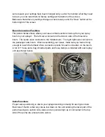
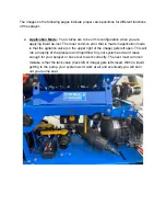
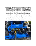
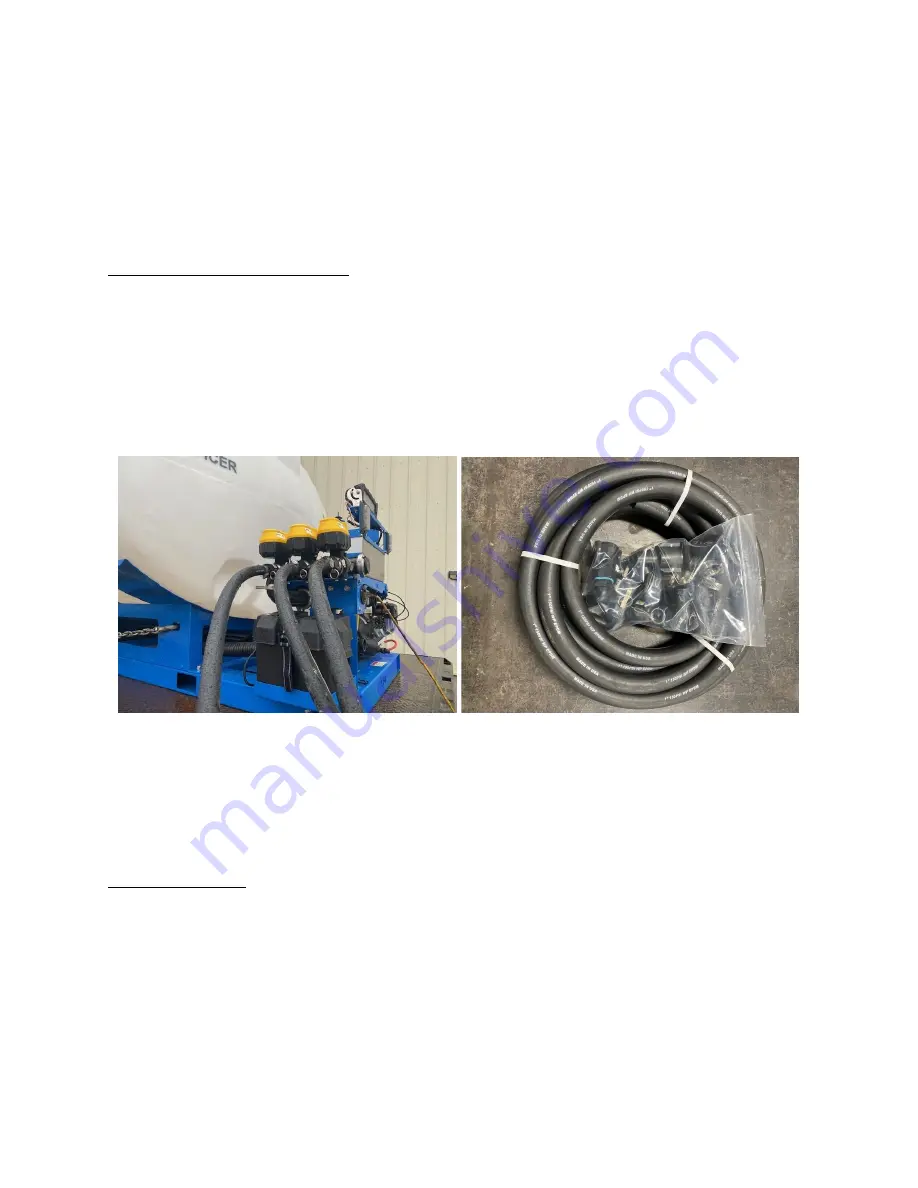
The picture below shows where your hose camlock sections hook up from your spray 
boom to your sprayer.  The left valve connects to the driver’s side of the three lane 
boom.  The center valve connects to the middle boom.  The right right valve connects to 
the passenger side boom.  When assembling your hoses, make sure you make it long 
enough to reach the furthest of two connection points for each connection on the boom. 
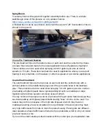
A roll of 1” hose and a bag of barbed parts and hose clamps is included with each spray 
unit as pictured below. 


Valve Functions 

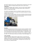
Proper valve positioning is vital to your sprayer working correctly for each given task. 
Best rule of thumb is that any valves low down on the unit entering the lower part of the 
pump housing are suction side valves and any valves high up or connected to the top 
side of the pump are pressure side valves. 


Содержание 1000 ASM

Страница 1: ...De Icing Applicator Manual 305 LP 500 ASM 750 ASM 1000 ASM 1600 ASM Automated Power Bundle...

Страница 2: ...ed by Honda and any Honda certified repair center All other parts on your equipment are warrantied against defects through VSI for one year from the date of purchase We do not offer a warranty on pump...

Страница 3: ...Use VERY IMPORTANT Your spray unit will heavily rely on the onboard deep cell battery That is why we have included an onboard charger battery maintainer Before first use plug this in overnight or unt...

Страница 4: ...ber can be found on the side of the control box You have now connected to the sprayer and have control over the unit No other devices can connect to a unit that is actively paired to a device If you w...

Страница 5: ...e Buster button is used when you are spraying a steady rate but have a section of snowpack ice or a high priority area that needs a higher application rate for a short stretch By pressing this button...

Страница 6: ...e center valve connects to the middle boom The right right valve connects to the passenger side boom When assembling your hoses make sure you make it long enough to reach the furthest of two connectio...

Страница 7: ...n application mode is that the agitation valve on the upper right of the image gets left open This will rob a majority of the pressure and liquid flow for your system and won t leave enough for your s...

Страница 8: ...osed The system will still fill this way as the valve has a hole that allows constant flow through the valve even when closed to protect the pump from being deadheaded but it will take an exceptionall...

Страница 9: ...bypass valve top right gets left open which will still allow the pump out to work but it will be substantially slower than if it is set up properly as shown Filter Each sprayer is equipped with a filt...

Страница 10: ...the top ones on each end and the central boom with a vertical camlock in the middle that sprays out of the jet nozzle holes in the stainless pipe These nozzles are to be used when spraying 70 120 gall...

Страница 11: ...clean so that the total control system can function properly Hose Reel The Hose Reel upgrade offers the ability to hand spray entryways sidewalks between cars and anywhere else that can t be reached w...

Страница 12: ...next item The image below shows your flow meter as viewed from the back of your spray unit These magnetic flow meters never require re calibration due to the use of different brine blends like a conv...

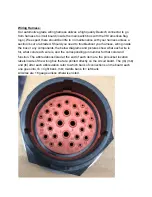
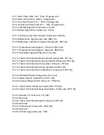
Страница 13: ...wiring inside the box or any components the below diagrams and pictures show what each wire is for what color each wire is and the corresponding pin number for that color and function The abbreviatio...

Страница 14: ...mb Pin 13 Total Control Remote Engine Starter Green Wire RF1 lb Pin 14 Total Control Remote Engine Kill Switch White wire RF2 lb Pin 15 Total Control Remote Choke Down Pink wire RF3 lb Pin 16 Total C...

Страница 15: ...above Wiring Box and Fuses To open your circuit board wiring box you will use a 1 phillips bit or screwdriver and remove the 6 screws that are countersunk in the front cover of your box The inside of...

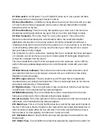
Страница 16: ...nnas one for WiFi to perform firmware updates diagnostics and one for Bluetooth to talk with your smart device 5 Main harness bulkhead This is where the main harness that connects to all of your elect...

Страница 17: ...ignal Additional Fuse There is an additional 40 amp automotive fuse inside of a water resistant fuse holder inside of the battery box If your battery is charged and your main switch is not illuminated...

Страница 18: ...ore current than the Honda motor charging system is able to supply back so if you will be running long shifts without time to charge your battery we would suggest not running your lights more than nec...

Страница 19: ...mall round magnetic puck in the image below is your GPS Puck Total Control Remote The signal receiver for the 2 4ghz total control remote can be seen next to the gps puck in the image above The remote...

Страница 20: ...off season storage of fuel IMPORTANT Avoid running the motor without liquid either due to not having your tank valve open while running or running your tank dry this will cause damage to the pump seal...

Отзывы: