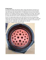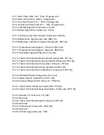
Be very cautious when using a test light or multimeter inside of your VSI Control
Box as shorting out a connection point could lead to your main computer being
rendered inoperable.
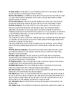
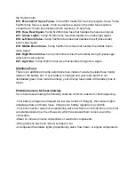
The color coded diagram above shows the wire color for each pin, keep in mind,
this
view is from the back of the plug (showing the wires going into the plug), so it is a
reversed/mirror image from the numbered image above.
Wiring Box and Fuses:
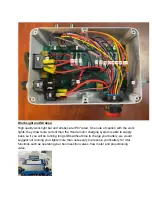
To open your circuit board/wiring box you will use a #1 phillips bit or screwdriver and
remove the 6 screws that are countersunk in the front cover of your box. The inside of
your circuit board/wiring box may look intimidating, but very little of what is inside will be
serviced by the end user.
The table below along with the corresponding labeled image on the following page will
help give you a better understanding of what is inside.
There is also a video here that runs through these items and the function of each fuse
inside your box:


