19
Electrical connections
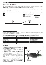
To connect the display, use the 7-pole cable supplied with the device, as shown in the following diagram. For
connection details, refer to the display manual supplied.
NOTE:
The cable is certified up to a maximum length of 4 meters: do not use longer lengths or splice the cable
to extend it.
These operations must only be performed by professionally qualified personnel before installing the device in
the false ceiling.
Functional test
To complete installation work, check the connections and carry out a functional test, according to the following
diagram:
In case of abnormal operation during testing, switch off the device and check connections.
Use
The device has continuous operation, with two
operating modes:
- Ventilation: the air taken from the outside is filtered
and sent inside; In this mode, air recirculation is
blocked.
- Purification: Air taken from the inside is disinfected by
the photocatalysis unit, filtered and re-sent inside; in
this mode, air inlet from the outside is blocked
In both modes, you can select 3 different air flow
intensities: min, med, max. speed.
NB In the event of prolonged absence, a switch can be
installed on the line to switch off the appliance.
All functions are managed by an external control panel.
See the relevant Instructions Manual for details on
operation.
ENGLISH
10
N
PE
L
1
2
BN
BU
GNYE
1
2-POLE SWITCH (DPST)
2
POWER CABLE
BU=Blue
BN=brown
GNYE=yellow/Green
Wired color code
Switch
Switch setting
Check
ON/OFF
ON
Ventilation active
High speed
MAX
Maximum ventilation
Medium speed
MED
Medium ventilation
Low speed
MIN
Minimum ventilation
ON/OFF
OFF
Minimum ventilation
11
Fresh air inlets
Supply air
Waste
recycled air
Содержание Vort Ariasalus 100
Страница 53: ......


