Precaution:
this symbol indicates that care must be taken to avoid damaging your product
!
• Do not make changes of any kind to the product.
• The appliance must be installed by a qualified
engineer.
• Make periodical visual inspections of the appliance
to ensure that it is completely intact. If any
imperfections are found, do not use the appliance
and contact your nearest Vortice Service Center
immediately.
• The electrical system to which the product is
connected must conform to current legislation.
• The appliance must be correctly connected to an
efficient earthing system, as foreseen by current
electrical safety regulations. If in doubt, ask for a
qualified engineer to check it.
• Only connect the appliance to the power
supply/outlet if the power supply/outlet has the
capacity to supply the maximum power absorbed by
the appliance. If it does not, consult a qualified
engineer at once
• Use a multi-polar, magnetic-thermal switch with
minimum contact gaps of 3 mm to install the
appliance.
• The air or fumes to be extracted must be clean (i.e.
free from grease, soot, chemical and corrosive
agents or explosive and inflammable mixtures) and
at a temperature of no greater than 90°C (194F)
• Do not cover or obstruct the appliance’s two inlet
and outlet grilles.
• Should the appliance be dropped or suffer a heavy
blow, have it checked immediately by an authorised
Vortice Service Center and, if repairs are required,
make sure that original Vortice parts are used.
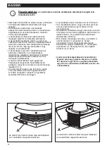
• The extraction fan, like all moving machines, may
generate vibrations. To avoid these vibrations being
transmitted to the structure of the building, apply
insulating washers 1), a hexagonal nut 2), anchor
brackets 3), and an insulating sleeve 4) (fig.6).
ACCESSORIES
Outer frame
Specially designed to aid installation of the Turret. The
four cramps, folded downwards, should be cemented
into the curb in correspondence with the ventilation
opening.
Drop-down shutter
In windy conditions, prevents air from re-entering
when the appliance is turned off. Mounted using the
screws or nuts and bolts supplied.
Extractor nozzle
To be mounted on the drop-down shutter (if not
connected to piping) to optimise extraction and reduce
noise levels. Mounted using the screws or nuts and
bolts supplied.
Protective grille
Satisfies the requirements of protecting moving parts,
if the appliance is installed in an accessible position.
Mounted using the screws or nuts and bolts supplied.
Three-position speed regulator switch
Suitable for regulating the operation of all TR-E
turrets. Allows remote selection of three different fan
speeds.
Electronic speed regulator
Suitable for regulating the operation of all TR-E
turrets.
The power-source data must be consistent with
the electrical data shown on the name plate A.
9
KAI
A
grilles
The pow er-source data m ust be consistent w ith
the electrical data show n on the nam e plate A .
The pow er-source data m ust be consistent w ith
the electrical data show n on the nam e plate A .
ENGLISH
10
A
●
If inverter speed controllers are used, make sure
that the fan is properly connected to a 230V (single
phase) or 400V (three phase) supply as required
by the inverter.
Содержание TORRETTE TR E
Страница 32: ...25 GREEK KAI A 32 A A A inverter inverter 230V 400V...
Страница 34: ...KAI A Vortice 3 Vortice Vortice Vortice 1 2 3 4 6 34 P CCK A 230 400...
Страница 36: ...27 KAI A 36 A...
Страница 49: ...2012 19 E EL 49...


