4
• Do not use this appliance for functions other than
those described in this booklet.
• After removing the appliance from its packaging,
ensure that it is complete and undamaged. If in
doubt contact a professionally qualified electrician or
Vortice*. Do not leave packaging within the reach of
children or infirm persons.
• Do not operate the appliance in the presence of
inflammable vapours (alcohol, insecticides, petrol,
etc.).
• Do not sit on the appliance or rest objects on it.
• Do not make modifications of any kind to this
appliance.
• Do not expose this appliance to the weather (rain,
sun, etc).
• Regularly inspect the appliance for visible defects. If
any faults are found, do not operate the appliance
but contact Vortice* immediately.
• Should the appliance be dropped or suffer a heavy
blow, have it checked immediately by Vortice*.
• Installation of the appliance, internal and
external cleaning, replacement of the spare
filters must only be carried out by a
professionally qualified electrician.
• The filter holder container must only be fitted to
Vortice ducting appliances such as Cubico or
Cubico SAL.
• The product is fitted with: a filter F6 associated with
a pre-filter G4. Do not use filters of types other than
the ones indicated.
• The side doors are used to fit the filters, and for
inspection and maintenance.
• The connection sides for air intake and expulsion
are fitted with panels that can be removed and/or
opened during installation to connect to the Cubico
appliances.
• The filter holder and the appliances must be
connected when the system is installed.
• Warning! Always follow the arrows indicating the
direction of air flow and the position of filters, to
ensure the filter holder is positioned correctly.
The pre-filter G4 at the air intake, the filter F6 at
the air outlet.
• Caution
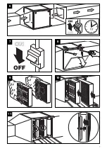
Before starting the ducting system, make sure
you follow the instructions given below:
a) Open the door giving access to the filters, remove
the stops by unscrewing the ball knobs and extract
the ball knobs from their housings.
b) Close the access door and run the ducting
system for a few minutes. (This operation serves to
clean out any impurities from the pipes).
c) Remove the protective PE film from around
the filters.
d) Stop the system, open the door giving access to
the filters and replace them, each one in its proper
housing, fixing them in position with the stops and
screwing the ball knobs into place. Always follow the
indications provided on the notice plates. The pre-
filter G4 at the air intake, the filter F6 at the air
outlet. Close the door and start the system again.
• Limits for use of the filters:
Continuous working temperature 80°C.
Relative humidity 90%.
• After installation, remove the protective film from the
plastic film-coated panel sheets.
Dimensions in mm (LxBxH) of the filter holders:
480 x 440 x 440 Cubico Filter Holder CF 7/7
520 x 480 x 480 Cubico Filter Holder CF 9/9
580 x 540 x 540 Cubico Filter Holder CF 10/10
680 x 640 x 640 Cubico Filter Holder CF 12/12
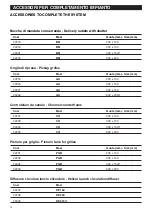
For the dimensions of pre-filters and filters, please see
the tables on the spare parts page.
COMPLIANCE WITH STANDARDS
In compliance with current regulations.
Warning:
this symbol indicates precautions that must be taken to avoid injury
!
WARNING - CAUTION
Caution:
this symbol indicates precautions that must be taken to avoid damaging the appliance.
!
*or an authorized Vortice dealer if you are outside the UK-Ireland territory
DESCRIPTION AND OPERATION
ENGLISH
The product you have purchased is a filter holder ele-
ment comprising a cube shaped container holding a
filter F6 associated with a pre-filter G4, indicated for
ducting systems and combinable with ventilating
tanks in the Cubico and Cubico SAL series.
The container has an extruded anodized aluminium
structure with plastic film-coated galvanized steel
panels. Two opening panels, with double safety lock
for inspection, maintenance and filter replacement,
two removable panels for connection to ventilating
tanks, and can contain two filters (provided).
Содержание CF
Страница 5: ...5 ESEMPIO DI APPLICAZIONE EXAMPLE OF APPLICATION 1 ...
Страница 7: ...7 7 8 5 9 5 10 11 6 ...
Страница 8: ...8 5 12 ...


