Fuse and Relay Box
The engine’s electrical system is protected against cir-
cuit overload by fuses and circuit breakers. Engine
electrical circuits may also be routed through relays.
All relays, breakers, and fuses for the driveline are
contained in a single fuse box. The box is covered and
is mounted on the top of the engine. If electrical sys-
tems such as power trim or ignition are not working,
check this box as a first step in troubleshooting the
problem.
WARNING!
Burn hazard. Oxygen sensor located above Fuse and
Relay Box cover may be very hot.
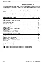
A label on the cover shows the location, type, size, and
other information for the relays, fuses, and breakers.
Part numbers are also provided.
The image is an example of one of these labels and
may not represent your engine. See the cover label on
your engine.
Spare fuses are located on the inside of the fuse box
cover. Remember to replace any spares that are used.
NOTICE!
Circuit breakers or fuses that repeatedly fail
indicate a problem that requires immediate attention.
See your Volvo Penta dealer.
EVC Diagnostic Function
See
Fault Handling
.
P0016590
P0019988
P0016589
Troubleshooting
122
47706354 08-2015 © AB VOLVO PENTA
Содержание V6-240
Страница 1: ...OPERATOR S MANUAL V6 240 V6 280 V8 300 V8 350 ...
Страница 88: ...51318 51319 51320 Operation 86 47706354 08 2015 AB VOLVO PENTA ...
Страница 175: ......
Страница 176: ...VPA 47706354 English 08 2015 ...


