


43
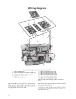
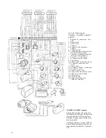
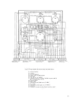
Fig. K2A. Wiring diagram. Engine
TAMD60A*, TAMD60B
1.
Batteries. Capacity see ”Technical
data”
2.
Master switch
3.
Starter motor
4.
Alternator
4x. Alternator (1600 W, optional equipm.)
5.
Voltage regulator
5x. Voltage regulator (optional equipm.)
Must not be fitted to engine.
6.
Fuses 50 A for standard alternator (80
A for 1600 W alternator)
7.
Fuses 25 A (in both cases)
8.
Oil pressure sender, engine
9.
Stop solenoid
10. Engine coolant temperature sender
11. Oil pressure sensor (for hour meter)
12. Speed sender
13. Oil pressure sender – reverse gear
14. Oil pressure sensor
15. Pressure sender – turbo
16. Engine coolant temperature sensor
17. Starter cut-out relay (only TAMD60B)
* TAMD60A engines
The cable from terminal 105 connects
to the starter motor terminal 50 and the
cable from terminal 110 connects di-
rectly to the alternator terminal 61.
If the large alternator is used (1600W)
a cable connects from the voltage re-
gulator terminal WL to terminal 110.
Relation mm
2
/AWG
mm
2
0.75
1.5
2.5
4
6
10
16
70
AWG 19
15 (16)
13
11
9 (10)
7
5
00
Cable areas are indicated in mm
2
for all
wiring diagrams. The corresponding si-
zes in AWG can be seen from the table.
Содержание AQD70C
Страница 1: ...INSTRUCTIONBOOK TAMD60A B TAMD70C D AQD70C D ...
Страница 52: ...7731201 5 English 7 1979 ...