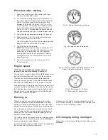
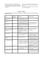
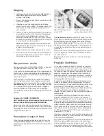
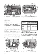
background image

28

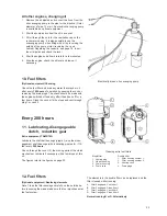
Seawater filter

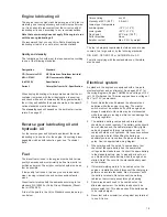
The filter (optional equipment) should be taken apart and
cleaned after every 200 hours of operation or more often if
necessary.

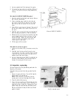
First close the bottom valve. Then screw the attaching
screws out of the cover (1). Lift up the cover and the ele-
ment and clean the element in the housing (2) carefully.
Refit the parts, open the bottom valve and check that there
is no leakage.

Every 600 hours

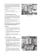
18. Lubricating oil filters, replacing

Replace the lubricating oil filters after every 600 hours of
operation, or at least once a year, although during the
running-in period after the first 100 hours.

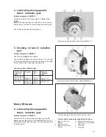
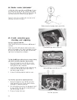
1.

Unscrew the oil filters and discard them. On AQD70D
and TAMD70D there is only one filter
.

2.

Oil the rubber gaskets on the new filters and check
their contact surfaces on the engine.

3.

Screw on the new filters until the gaskets make contact.
Then tighten a further half turn but no more.

4.

Check for leakage after starting the engine.

5.

Check the oil level in the engine.

19. Changing oil in the reduction

gear

Optional equipment, TAMD70D

Change the oil after every 600 hours of operation or at
least once a year.

During the running-in period the oil should be replaced af-
ter the first 100 hours of operation.

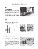
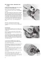
Drain the oil through the bottom plug (6), see figures page
18. Alternatively the oil can be sucked out with the help of
the oil scavenging pump.

Collect the oil carefully and hand it over to a service sta-
tion or disposal depot. Never pollute the water by discar-
ding the oil overboard.

Clean the ventilation cap above the filler opening on the
Twin Disc reduction gear in connection with changing the
oil.

Concerning oil quantity and quality, see ”Technical data”.

20. Valve clearance, checking

Check the valve clearance after every 600 hours of opera-
tion, or at least once a year. This should be carried out by
authorized service personnel. Concerning clearances, see
under ”Technical data”. Note! The clearance must never
be checked while the engine is running, but should al-
ways be carried out with the engine switched off, either
with a cold engine or when it is at operating temperature.

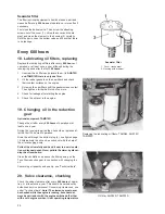
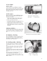
Seawater filter

1. Cover, transparent
2. Housing with element

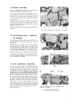
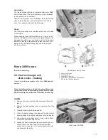
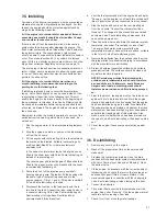
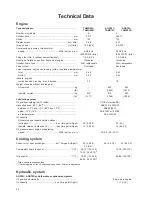
Replacing the lubricating oil filters, TAMD60, AQD70C,
TAMD70C

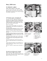
Oil filter, AQD70D, TAMD70D

Содержание AQD70C

Страница 1: ...INSTRUCTIONBOOK TAMD60A B TAMD70C D AQD70C D ...

Страница 2: ...ial number of the engine and its equipment Volvo Penta dealers and service stations are equipped with the special tools required and they also have extensive stocks of parts so that you are always sure of obtaining genuine parts for servicing and repairing Always contact your local Volvo Penta representative for service and spares A warranty certificate is provided with every engine giving you inf...

Страница 3: ...stem Electrical system 19 32 Wiring diagram 42 47 Servicing Page Servicing scheme 20 Lubrication and checks 21 Engine 21 24 Reverse gear 21 31 Disengageable clutches and reduction gears23 25 28 Hydraulic system 24 31 Coolant level 22 Fuel filters 25 26 Venting 26 Air cleaner 29 V belts 27 Turbo compressor 27 36 Lubricating oil filters 28 31 Zinc electrodes 27 Cooling system 27 29 33 Electrical sys...

Страница 4: ...dealer for assistance This symbol is used throughout the instruction manual and on the product to bring your atten tion to points of safety related information Always read such information thoroughly Warnings in the instruction manual have the following order of priority WARNING Warns for the risk of physical injury severe damage to the product or other property or serious malfunctions that may oc...

Страница 5: ...with directions in the instruction manuals and that the safety equipment on board is in good working order Daily inspection Make a habit of visually inspecting the engine and en gine room before starting before starting the engine and after stopping when the engine has been turned off This will help you to quickly detect any fuel coolant or oil leaks and any other abnormalities that have occurred ...

Страница 6: ...or in any other way changing the setup of the cover as well Get in touch with your boat dealer for help in obtaining the best solution for your boat Remember Safety equipment life jackets for everyone on board communication equipment distress rockets approved fire extinguisher bandages life buoy anchor paddle torch etc Spare parts and tools Impeller fuel filter fuses adhesive tape hose clips engin...

Страница 7: ...nge the centre of grav ity Special lifting devices may be required to obtain the right balance and safe handling Never perform service on an engine suspended only from a lifting de vice Beforestarting Refit all guards and covers that have been removed before starting the engine Make sure there are no tools or other objects left on the engine A turbocharged engine must never be started without the ...

Страница 8: ...tc must never theless be opened or dismantled while the engine is warm the filler cap must be opened carefully to re lease the pressure before removing it completely and starting work Note that the coolant can still be hot and cause burn injuries Lubricating system Hot oil can cause burn injuries Avoid skin contact with warm oil Make sure the lubricating system is depressurised before starting wor...

Страница 9: ...er gear housing port side Fig 1 Engine TAMD60B 1 Heat exchanger 2 Coolant filler cap 3 Protecting plate 4 Fuel fine filters 5 Engine oil filler cap 6 Liquid cooled exhaust manifold 7 Filter crankcase ventilation 8 Oil dipstick reverse gear 9 Electric connection box with fuses 10 Oil dipstick engine 11 Stop solenoid 12 Injection pump 13 Alternator 14 Charging regulator Fig 2 Engine TAMD60A 1 Turbo ...

Страница 10: ... supplies lubricating oil to all the lubricating points in the correct quantities at all engine speeds The pistons in the 70 type engines are cooled by oil fed through special nozzles located in the engine block The lower part of the crankcase functions as an oil contai ner The fuel system is well protected from interruptions during running by means of effective replaceable fuel fine filters On th...

Страница 11: ...and cooled from the fresh water cooling sys tem In order to further increase the supply of oxygen the air to the engine is cooled down by an after cooler located after the compressor at the intake manifold The Aquamatic models are provided with a hydraulic pump and a special connection flange at the reverse gear Other wise they are similar to the inboard engines The hydraulic pump fitted at the re...

Страница 12: ...ey can be inserted and removed Position 1 is not used turn key past this position Position II running position Position S pre heater engaged Does not apply to TAMD60 See also fig 19 2 Control lamp does not apply to TAMD60 This lights up when the air pre heater is engaged key turned to position S It remains alight while the air pre heater is engaged approx 120 sec The pre heater disengages automati...

Страница 13: ...era ture becomes excessive or its oil pressure too low Either lamp 17 or 18 will light and indicate the type of fault which has arisen 21 Pressure gauge for the turbo compressor charging pressure Concerning the pressure see Technical Data page 40 Fig 8 Flying Bridge instrument panel optional equipment The numbering on figs 7 and 8 is similar Flying Bridge instruments which have the same function a...

Страница 14: ...m engine When engaging and disengaging the clutches the engine speed must not exceed 13 3 r s 800 r min Running The following instructions apply to engines which have both standard instrumentation and optional instrument equip ment In the case of standard instruments only the instructions apply where appropriate Procedure before starting 1 Coolant level Check that the level is about 5 cm below the...

Страница 15: ...ween the two marks on the dipstick Repeat the check for Twin Disc reverse gears whilst idling with the control in the neu tral position since this indicates the true level for this type of reverse gear The oil level in the Borg Warner and SCG reverse gears should be checked when the engine is not running The oil level will lie above the max mark when the engine has been stationary long enough for ...

Страница 16: ...s press the starter button 9 fig 7 immediately when the control lamp 7 lights The lamp 7 which lights for about 60 seconds lights up 60 seconds after the lamp 2 About 2 minutes after the key has been released from position S the pre heater disengages automatically and the lights 2 and 7 go out The TAMD60 engines are not provided with the control lamps mentioned in the point above and are therefore...

Страница 17: ...and favourable operation Do not run for long periods of time with the engine speed below 23 3 r s 1400 r min with the engine under load If the speed tends to drop gradually this may be due to dirt or marine growth on the bottom of the boat For this reason the hull below the waterline should always be thoroughly cleaned in such cases and treated with anti fouling paint before other measures are tak...

Страница 18: ... kp cm2 21 p s i Engine coolant tempera ture 10 65 95 C 150 203 F normally during operation If the lamp lights and the siren is heard the engine temperature is too high Stop the engine Re medy the fault Warning lamp coolant temperature 18 The light should not come on Lights if engine temp exceeds approx 95 C 203 F the siren is also heard Charging voltage 5 During normal running approx 28 volts for...

Страница 19: ...st The freshwater system should also be drained or Volvo Penta glycol or another glycol of approved quality added Before draining stop the engine remove the filler cap and close the bottom valve Then open the drain cocks in the fresh water and seawater system There may also be cocks at the lowest points of the cooling water and the ex haust lines Remove the cover on the seawater pump and the cover...

Страница 20: ...out glycol is used during the summer do not add anti corrosion agent which can damage the light alloy parts in the cooling system In order to avoid corrosi on the easiest method is to use a suitable mixture of Volvo Penta red glycol all year round It should be changed every autumn Fig 32 AQD70D TAMD70D F Fresh water cocks S Seawater cocks 1 Fresh water filler cap 2 Venting cock Fig 31 All engines ...

Страница 21: ... winter grade 25 C 13 F Flash point 40 C min 104 F Solid impurities None Sulphur content Max 0 5 by weight The fuel oil property requirements stated above are also covered to a large extent by the following standards DIN 51601 CEC ERF D1 or ASTM D975 No 2 D Fuel oils complying with these standards can therefore also be used Electrical system As standard the engines are equipped with a two pole ele...

Страница 22: ...g All the measures listed above except for No 32 should be carried out at least once a year even if the running time in the schema has not been reached 1 The interval can be increased to 400 500 operating hours under favourable conditions Servicing scheme The numbering in the scheme below lists the servicing operations described in the following pages under the cor responding numbers Servicing wor...

Страница 23: ...3 Imp gall US gall litres AQD70 27 0 6 7 0 TAMD70 27 0 6 7 0 16 0 3 5 4 2 18 TAMD60 20 0 4 4 5 3 0 13 0 2 9 3 4 18 2 Reverse gear oil level Check the oil level daily with the dipstick and add oil if ne cessary When checking the oil level in the Twin Disc rever se gear the engine should be idling and the operating con trol in neutral position The oil level in the Borg Warner and SCG reverse gears s...

Страница 24: ...gines small quantities of coolant requi red for topping up can be added to the expansion tank but otherwise the coolant should always be filled directly into the heat exchanger through the hole for the hexagon plug until the engine is completely full and air vented Then clo se the venting cock at the turbo and refit the hexagon plug on the heat exchanger Thereafter fill the expansion tank with app...

Страница 25: ... reduction sity dm3 litres gear qts Rockford BW 203 mm 8 Engine oil SAE 30 approx 1 1 254 mm 10 Engine oil SAE 30 approx 1 5 1 5 Twin Disc Engine oil SAE 40 approx 1 1 or Hypoid oil SAE 80 Every 50 hours 6 Lubricating disengageable clutch reduction gear Optional equipment TAMD70D Lubricate the inner support bearing nipple 4 every 50 hours Unscrew the plug 4 for Rockford BW 203 mm 8 power take off ...

Страница 26: ...ing oil Change the oil in the engine after every 100 hours of ope ration and when the engine is warm However during the running in period the oil should be changed for the first time after 25 hours of operation Do not use flushing oil for cleaning the crankcase Only drain pump out the old oil carefully NOTE Collect the old oil carefully and hand it over to a service station or disposal depot Never...

Страница 27: ...en off for a few hours Close the cock or fit the plugs and vent through plug 1 or cock 3 Every 200 hours 11 Lubricating disengageable clutch reduction gear Extra equipment TAMD70D Lubricate the shaft ball bearings nipple 3 and the disen gagement shaft bearings with lubricating nipples 5 if fit ted every 200 hours Check through the cover 2 the moving parts of the clutch mechanism Lubricate if neces...

Страница 28: ...ntering the fuel system Replacing 1 Wash the filter head carefully especially at the lower edge then screw off both filters and discard them 2 Check that the new filters are absolutely clean and that the gaskets are undamaged 3 Screw on the filters by hand until the gaskets touches the filter head Then tighten them one further half turn but not more 4 Vent the fuel system according to the followin...

Страница 29: ...ten the hose clamps or replace the hose if necessary Any leakage in the lubricating oil and cooling water lines must be remedied immediately in order not to impair the function of the turbo compressor 17 Zinc electrodes checking Check the zinc electrodes after every 200 hours of opera tion First close the bottom valve and drain off some of the coolant Screw out the electrodes and scrape or brush o...

Страница 30: ...l equipment TAMD70D Change the oil after every 600 hours of operation or at least once a year During the running in period the oil should be replaced af ter the first 100 hours of operation Drain the oil through the bottom plug 6 see figures page 18 Alternatively the oil can be sucked out with the help of the oil scavenging pump Collect the oil carefully and hand it over to a service sta tion or d...

Страница 31: ...is filter element should be replaced with a new one after every 600 hours of opera tion 22 Injectors checking After every 600 hours of operation the injectors should be cleaned and checked with regard to opening pressure spray pattern and leakage by authorized personnel For injector values see Technical data 23 Cooling system checking Check the cooling system for leakage and blockage after every 6...

Страница 32: ...e Rockford BW type clutches have a screw on locking plate which retains the adjustment ring in position 1 Remove the inspection cover Set the lever to the disengaged position and turn the clutch so that the locking plate becomes accessible 2 Loosen the locking plate and turn the adjustment ring to the left so many notches that powerful force is required to engage the lever 3 Screw on the locking p...

Страница 33: ...m plug Collect the used oil and hand it over to a service station or disposal depot Never pollute the water by discarding the oil overboard After filling oil start the engine and run it for a few minutes at idling speed Then check the oil level on the Twin Disc gear with the engine running at idling speed and the gear in Neutral The level in the Borg Warner and SCG reverse gears should be checked ...

Страница 34: ...is marked DF Remove the cover and unscrew both the brush holder screws Carefully lift out the brush holder taking care not to damage the brushes Check that the brushes run easily in their holders and that at least 5 mm of the brushes project and that the brush ca bles are not damaged and are well soldered If necessary replace the complete brush holder including the brushes If the slip rings are sc...

Страница 35: ... cooler cleaning Clean the inserts once a year or after every 2400 hours of operation Close the bottom valve and drain the coolant before car rying out any work on the cooling system After comple ting work pump the coolant out of the boat if necessary TAMD60 1 Remove the cover over the after cooler and lift up the insert 2 Remove the heat exchanger end cover and pull out the insert 3 Clean the ins...

Страница 36: ...from the block applies to TAMD60A and pull out the cooler insert The insert can only be pulled out forwards because it is provided with a flange at the front end 3 Wash the insert in white spirit and blow it dry with compressed air Clean the end sides of the inserts with a wire brush and clean the inside of the tubes with a suitable brush Clean the housing 4 Use new gaskets and fit the parts Oil c...

Страница 37: ...h the coolant Oil coolers for all reverse gears 1 Loosen both the ends of the oil cooler and remove the insert 2 Wash the insert in white spirit and blow dry using compressed air Clean the end sides of the insert with a wire brush and clean the inside of the tubes with a suitable brush Clean the housing 3 Use new sealing rings when fitting Do not tighten the screws too hard Normally there should b...

Страница 38: ...as the general condition of the unit This check should be carried out by authorized personnel If necessary replace the turbo compressor with a new or reconditioned unit Always fit new oil filters and change the engine oil when replacing the turbo compressor Fill the turbo compressor bearing housing with 0 1 litre 0 1 quart of oil before con necting the oil delivery pipe 34 General checking It is d...

Страница 39: ...sed 5 Disconnect the fuel line to the feed pump and the re turn line to the tank Connect the lines using hoses to a vessel containing 1 3rd Volvo Penta lubricating oil Rust proofing oil of type Esso Rust Ban 623 or equivalent and 2 3rds diesel fuel 6 Vent the fuel system and start the engine See chapter Running Let the engine run at rapid idle until about 2 litres 2 quarts have been consumed from ...

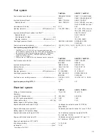
Страница 40: ...d version kg 670 810 820 lb 1477 1786 1808 Lubricating system Oil quality according to API system CD For Service DS Viscosity above 20 C 68 F SAE 30 Alt 20W 30 between 20 C and 10 C 68 F and 14 F SAE 20 20 W below 10 C 14 F SAE 10W or 10W 20 all temperatures SAE 15W 40 Oil capacity AQ version and inboard version without inclination dm3 Imp gall USgall 20 4 4 5 3 27 6 7 Inboard version inclination ...

Страница 41: ...rod TAMD60B AQD70D TAMD70D Fuel injection pump Bosch PES6MW 100 320 PE6P 110A 320 RS1004Z RS260Z Injectors holders Bosch KBEL 95 P 9 4 KBEL 95 P 9 4 Nozzles Bosch DLLA 150 P 28 DLLA 150 P 32 Hole diameter mm 4 x 0 34 3 x 0 46 Opening pressure MPa kp cm2 p s i 24 245 3485 27 275 3911 Centrifugal governor Bosch RSV 250 1400 EP RSV 250 1250 MW2 308 PO 374 2R Fuel feed pump working pressure kPa kp cm2...

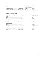
Страница 42: ...se gear TAMD60 AQD70 TAMD70 Twin Disc model MG502 MG506 Ratios 1 5 1 2 1 2 5 1 1 1 1 5 1 2 1 3 1 Oil quality and viscosity Same as in engine Oil capacity including cooler dm3 imp gall US gall 2 5 0 6 0 7 6 5 1 4 1 7 Working pressure at oil temperature 82 C 180 F engaged 30r s 1800 r min MPa kp cm2 p s i 2 2 2 4 21 8 24 0 2 1 2 2 21 22 5 310 340 300 320 at cruising speed min MPa kp cm2 p s i 1 93 1...

Страница 43: ...Reduction gear Permitted engine speed with engaged power take off r s r min 15 0 30 0 900 1800 Twin Disc Reduction 3 6 1 Size mm in 203 8 Weight approx kg lb 75 165 Oil quality and viscosity Engine oil SAE 40 alt Hypoid oil SAE 80 Oil capacity dm3 Imp qts USqts 1 0 9 1 1 Borg Warner Rockford Reduction 1 1 2 8 1 Size 1 1 2 8 1 mm in 203 8 alt 254 10 Weight approx 1 1 kg lb 65 143 2 8 1 kg lb 75 165...

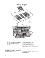
Страница 44: ...Contact male and female Black 8 pole 6 Contact male and female Black 8 pole 7 Contact male and female Green 8 pole Male and female contacts belonging together have the same colour If panel D is fitted but not B contact No 1 from the Flying Bridge instrument panel is wired to contact No 2 from the engine However contacts Nos 1 and 7 should not be wi red together when panel D is not fitted When only...

Страница 45: ... hour meter 12 Speed sender 13 Oil pressure sender reverse gear 14 Oil pressure sensor 15 Pressure sender turbo 16 Engine coolant temperature sensor 17 Starter cut out relay only TAMD60B TAMD60A engines The cable from terminal 105 connects to the starter motor terminal 50 and the cable from terminal 110 connects di rectly to the alternator terminal 61 If the large alternator is used 1600W a cable ...

Страница 46: ...mperature sender 11 Oil pressure sensor for hour meter 12 Speed sender 13 Oil pressure sender reverse gear 14 Oil pressure sensor 15 Pressure sender turbo 16 Engine coolant temperature sensor 17 Relay box for air pre heater 18 Solenoid valve 19 Flame glow plug 20 Starter cut out relay only TAMD70D AQD70D TAMD70C AQD70C engines Cables from terminal 105 connect to the starter motor terminal 50 and t...

Страница 47: ... 35 Stop button 36 Time relay not on TAMD60 37 Holding current relay Omitted on TAMD60 but green cable 2 5 from 35 is connected to on 33 38 Series resistance 39 Starter button 40 Indicating lamp pre heater not on TAMD60 41 Rev counter 42 Indicating lamp start engine not on TAMD60 43 Key switch 44 Rheostat for instrument lighting Switch on earlier models ...

Страница 48: ... etc 51 Instrument lighting 52 Oil pressure gauge reverse gear 53 Alarm separator 54 Pressure gauge turbo 55 Extra switches max 5 A per switch 56 Charging warning lamp 57 Oil pressure warning lamp engine 58 Engine coolant temperature warning lamp 59 Siren 60 Hour meter ...

Страница 49: ...ator The free blue 1 5 cable should be connected to 104 on the engine terminal box Fig K6 Wiring diagram Flying Bridge instrument panel 81 Battery charging warning lamp 82 Oil pressure warning lamp engine 83 Coolant temperature warning lamp 84 Extra switches max 5 A per switch 85 Alarm separator 86 Siren 87 Instrument lighting 88 Switch instrument lighting 89 Stop button 90 Rev counter 91 Starter ...

Страница 50: ... 26 Fuel filter change 25 26 Fuel quality 19 Fuses 33 43 44 G Glycol 17 18 Get you home device 17 H Hydraulic oil 19 38 I Inhibiting 37 Injection pump 36 39 Injectors 29 39 Instruments 10 11 M Maintenance see Servicing 20 Manoeuvring Forward Reverse 12 Manoeuvring controls 12 Master switch 19 43 44 N Number plates 7 O Oil capacities 21 23 40 41 Oil change engine 24 25 reverse gear 31 Oil filters c...

Страница 51: ...iven in r s revolutions per second earlier unit r min revolutions per minute Volume is given in dm3 cubic decimetre earlier unit l litre earlier unit Imp gall British Imperial gallon earlier unit USgall United States gallon Personal Information Name Address Tel Nearest Volvo Penta Dealer Service Workshop Name Address Tel Information Engine Type of engine Serial Number Type of reverse gear No Ratio...

Страница 52: ...7731201 5 English 7 1979 ...

Отзывы: