background image

18

5.1 GAS SUPPLY INSTALLATION

Inspect the entire installation including the gas meter, 
test for tightness and purge. Refer to BS 6891 (I.S. 813 
in ROI) for specifi c instruction.

5.2 THE HEATING SYSTEM

The appliance contains components that may become 
damaged or rendered inoperable by oils and/or debris 
that are residual from the installation of the system, 
consequently it is essential that the system be fl ushed 
in accordance with BS 7593 Code of Practice and the 
following instructions.

5.3 INITIAL FILLING OF THE SYSTEM

Remove appliance casing as described in 4.7.1, identify 
the automatic air release valves (AAV) and loosen the 
dust cap/s by turning the cap anti-clockwise one full turn.
Ensure all manual air release valves located on the heat-
ing system are closed.  Proceed to fi ll the system via the 
feed and expansion tank and begin venting all manual 
air release valves, starting at the lowest fi rst. 
Once the system has been fi lled. Inspect the system for 
water soundness, rectifying any leaks.

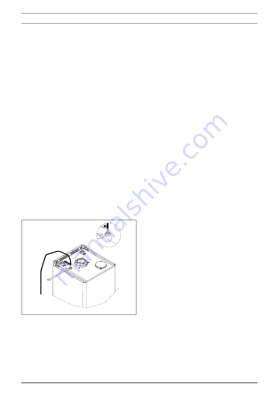
5.3.1 MANUAL AIR RELEASE (Fig. 22)

When the boiler has been fi lled for the fi rst time or the 
system has been drained and refi lled, it will be necessary 
to release any air that may have become trapped within 
the appliance heat exchanger.  
Slacken the bleed screw until water is released and then 
close.
IMPORTANT, THERE ARE NO OTHER MANUAL AIR 
RELEASE VALVES LOCATED ON THE APPLIANCE.

5.4 INITIAL FLUSHING OF THE SYSTEM

The whole of the heating system must be fl ushed both 
cold and hot as detailed in 5.8. Open all radiator and/or 
heating zone valves. 
Drain the boiler and system from the lowest points. 
Open the drain valve full bore to remove any installation 
debris from the boiler prior to lighting. 
Refi ll the boiler and heating system as described in 5.3.

5.5 PRE-OPERATION CHECKS

Before attempting the initial lighting of the appliance, the 
following checks must be carried out:

 Ensure all gas service valves from the meter to the 

appliance are open and the supply pipe has been 
properly purged;

 Ensure the proper electrical checks have been car-

ried out, (see 7.8) particularly continuity, polarity, and 
resistance to earth;

 Ensure the 3 AMP fuse – supplied with the appliance 

– has been fi tted.

 Ensure the system has been properly fi lled and vented.

  Ensure the fl ue system has been fi tted properly and in 

accordance with the instructions.

 out, (see 7.8) particularly continuity, polarity, and resist-

ance to earth;

  Ensure the 3 AMP fuse – supplied with the appliance 

– has been fi tted.

  Ensure the system has been properly fi lled and vented.

  Ensure the fl ue system has been fi tted properly and in 

accordance with the instructions.

5.6 INITIAL LIGHTING

Ensure the electrical supply to the appliance is switched 
on. Ensure any external controls are switched to an ‘ON’ 
position and are calling for heat.
Move the selector switch to the ON position, the appliance 
will now operate as described in 1.2. 
Should the appliance fail to ignite, refer to 5.6 and/or 
section 7 (mode of operation & faultfi nding).

NOTE
When power is restored to the PCB and/or the PCB 
is powered for the fi rst time, the appliance will enter 
a 2-minute purge cycle whereby only the pump will 
run for 15-seconds then off for 15-seconds.

5.7.1 CHECKING GAS PRESSURE AND COMBUS-
TION ANALYSIS

The appliance is factory set so should require no addi-
tional adjustment once installed. However to satisfy the 
requirements of GSIUR 26/9 (I.S. 813 ROI), it will be 
necessary to gas rate the appliance using the gas meter 
that serves the appliance and carry out a combustion 
analysis check in accordance with BS 7967 (UK) to en-
sure that correct combustion is occurring, see fl ow chart 
on page 38.
Additionally, if the gas valve has been adjusted, repla-
ced, or the appliance has been converted for use with 
another gas type, then it becomes necessary to carry 
out a combustion analysis check to ensure that correct 
combustion is occurring.
If there are no means to carry out a combustion analysis 
check, then it will not be possible to complete the com-
missioning procedure.
Details on how to carry out the combustion analysis can 
be found in section 7.

IMPORTANT
It’s imperative that a suffi cient dynamic – gas – pres-
sure is maintained at all times. Should the dynamic 
gas pressure fall below an acceptable level, the ap-
pliance may malfunction or sustain damage.

SECTION 5      COMMISSIONING

Fig. 22

Содержание MYNUTE 15 VHE

Страница 1: ...TO BE RETAINED BY USER Mynute VHE High efficiency open vent boiler Vok ra is a licensed member of the Benchmark scheme which aims to improve the standards of installation and commissioning of domestic...

Страница 2: ...5 3 Initial filling of the system 18 5 4 Initial flushing of the system 18 5 5 Pre operation checks 18 5 6 Initial lighting 18 5 7 Checking gas pressure combustion analysis 18 5 8 Final flushing of th...

Страница 3: ...voltage directive 2006 95 EC Directive 2009 125 EC Ecodesign for energy using ap pliances Directive 2010 30 EU Indication by labelling of the con sumption of energy by energy related products Delegate...

Страница 4: ...e temperature selector clockwise to increase the boiler outlet temperature or counter clockwise to reduce the outlet flow temperature 2 digit LED display Displays the current outlet temperature of the...

Страница 5: ...sure flame stability at the burner Once successful ignition has been achieved the electronic circuitry increases the gas rate to 75 for a period of 15 minutes Thereafter the boiler s output will eithe...

Страница 6: ...50mm from casing or 25mm above flue elbow whichever is applicable Bottom 150mm Front 600mm 2 5 Connections Flow return 22mm Gas 15mm Condense 21mm 2 6 Electrical Power consumption Watts 35 Supply V Hz...

Страница 7: ...ed 15 kW Seasonal space heating energy efficiency s 93 For boiler space heaters and boiler combination heaters useful heat output For boiler space heaters and boiler combination heaters useful efficie...

Страница 8: ...3 GAS SUPPLY The gas meter as supplied by the gas supplier must be checked to ensure that it is of adequate size to deal with the maximum rated input of all the appliances that it serves Installation...

Страница 9: ...ins electricity supply must allow for complete isolation from the supply The preferred method is by using a double pole switch with a contact separation of at least 3mm The switch must only supply the...

Страница 10: ...top of the boiler to the bottom of the F E tank shall be no less than 1 metre whilst the maximum distance shall be no greater than 30 metres The distance between the bottom of the F E tank and the hi...

Страница 11: ...ther watervapourwillcondense on leaving the terminal the effect of such pluming must be considered If installed less than 2m above a pavement or platform to which people have access including balconie...

Страница 12: ...he combined feed and vent pipe shall be unrestricted 3A 11 2 ALTERNATIVE CLOSE COUPLED ARRANGEMENT If necessary or if preferred a close coupled arrange ment for the feed and expansion pipe work can be...

Страница 13: ...if applicable 4 5 FITTING THE FLUE The top flue outlet permits both horizontal and vertical flue applications to be considered alternatively the Vokera twin flue system can be utilised if longer flue...

Страница 14: ...d an appropriate type and quantity of fixing should be used to ensure that the bracket is mounted securely Once the bracket has been secured to the wall attach the rear flue terminal to the appliance...

Страница 15: ...730mm 208mm Using the dimensions given in fig 12 as a reference mark and cut a 115mm hole in the ceiling and or roof X X 139 mm Fit the appropriate flashing plate to the roof and insert the vertical...

Страница 16: ...be given to the fact that there is the possibility of a small amount of condensate dripping from the terminal Ensure that the entire flue system is adequately sup ported use at least one bracket for...

Страница 17: ...centric to twin converter The last twin flue pipes must be pushed 50mm onto the male spigots of the concentric to twin converter You must ensure that the entire flue system is properly supported and c...

Страница 18: ...iled instructions ANY EXTERNAL CONTROL OR WIRING MUST BE SERVED FROMTHE SAME ISOLATOR AS THAT OF THE APPLIANCE The supply cable from the isolator to the appliance must be 3 core flexible sized 0 75mm...

Страница 19: ...fig 21 Pass the pump cable first through the cable anchorage point and then through the cable glands Connect the pump cable wires LIVE NEUTRAL EARTH to their corresponding terminals Live brown Neutral...

Страница 20: ...e 7 8 particularly continuity polarity and resistance to earth Ensure the 3 AMP fuse supplied with the appliance has been fitted Ensure the system has been properly filled and vented Ensure the flue s...

Страница 21: ...ECURED ENSURE ALL PIPE WORK IS RE CHECKED FOR TIGHTNESS RE FIT APPLIANCE CASING COMPLETE BENCHMARK CHECKLIST FOR UK ONLY Complete details of the boiler controls installation and commissioning in the B...

Страница 22: ...pliancedesignspecifica tion Anydeteriorationinperformancemustbeidentified and rectified without delay Check that the burner and main heat exchanger are clean and free from any debris or obstruction Ch...

Страница 23: ...e unit Disconnect the electrical plug and leads from the gas valve slacken and unscrew gas valve inlet and outlet connections Please note the sealing washers A must be discarded and replaced with new...

Страница 24: ...cations Step 4 fig 29 Locate and remove the 3 nuts B that secure the fan flue assembly to the heat exchanger The fan flue assembly can now be removed with care Step 5 The burner can now be removed wit...

Страница 25: ...he appliance ease the control panel from its location Step 2 Disconnect all wiring connections from the flue fan as sembly and heat exchanger Step 3 Slacken the gas pipe A at the outlet connection and...

Страница 26: ...epumpwillrunfor15 secondsthenofffor15 seconds and will not fire until this period has elapsed 7 2 3 HEATING MODE With the selector switch in the ON position and any additional controls time clock prog...

Страница 27: ...G Locate and gently turn the HTG trimmer till the minimum value fan speed is obtained and check that it corre sponds with the appropriate CO2 value Minimum for the respective appliance If the CO2 read...

Страница 28: ...nce terminal strip fig 21 NOTE Should it be found that the fuse has failed but no fault is indicated a detailed continuity check will be required to trace the fault A visual inspection of components m...

Страница 29: ...uity If the boiler still fails to respond refer to the detailed faultfinding flowcharts located at the end of this section CODE CAUSE ALARM TYPE ACTION AL10 Ignition failure not flame sensed con dense...

Страница 30: ...YPICAL CONTROL APPLICATIONS The appliance can be used with the following controls Single channel voltage free time clocks Programmable room thermostats Externaltwin channelprogrammers Theappliancecan...

Страница 31: ...nsformer FS Flow thermistor NTC RS Return thermistor NTC AD02X Main PCB CN1 CN5 Connection to PCB high voltage X4 X9 Connection to PCB low voltage F O H T Flow over heat thermostat H E T Heat exchange...

Страница 32: ...30 FUNCTIONAL DIAGRAM 8 4 1 S Plan with Vokera 2 channel programmer 8 4 2 Y Plan with Vokera 2 channel programmer Fig 40 Fig 41 N L E...

Страница 33: ...he meter must be purged and checked for gas soundness 10 6 CORRECTING THE CO2 VALUES ADJUSTING THE GAS VALVE THE GAS VALVE MUST BE SET UP OR ADJUSTED WITHTHE AID OF A PROPERLY CALIBRATED FLUE GAS ANAL...

Страница 34: ...If different adjust the gas valve according to the above 10 8 APPLIANCE FAN SPEEDS The appliance fan speeds require to be checked and or adjusted prior to making any adjustments to the gas valve or i...

Страница 35: ...tabilise YES Is CO less than 350ppm AND CO CO2 ra o less than 0 004 NO Boiler is opera ng sa sfactorily No further ac ons required Ensure test points are capped boiler case is correctly replaced and a...

Страница 36: ...FRPPLVVLRQLQJ FKHFNOLVW completed in full 7R LQVWLJDWH WKH ERLOHU JXDUDQWHH WKH ERLOHU QHHGV WR EH UHJLVWHUHG ZLWK WKH PDQXIDFWXUHU ZLWKLQ RQH PRQWK RI WKH LQVWDOODWLRQ 7R PDLQWDLQ WKH ERLOHU JXDUDQW...

Страница 37: ...HU LQWHUORFN 3URYLGHG ALL SYSTEMS 7KH V VWHP KDV EHHQ XVKHG DQG FOHDQHG LQ DFFRUGDQFH ZLWK 6 DQG ERLOHU PDQXIDFWXUHU V LQVWUXFWLRQV Yes KDW V VWHP FOHDQHU ZDV XVHG KDW LQKLELWRU ZDV XVHG 4XDQWLW OLWUH...

Страница 38: ...SKRQH 1R DV VDIH UHJLVWHU 1R 5HFRUG W PD UDWH 2 SSP AND 2 W PLQ UDWH KHUH 3RVVLEOH 2 SSP AND 2 RPPHQWV 6LJQDWXUH SERVICE 04 DWH QJLQHHU QDPH RPSDQ QDPH 7HOHSKRQH 1R DV VDIH UHJLVWHU 1R 5HFRUG W PD UDW...

Страница 39: ...37...

Страница 40: ...38...

Страница 41: ......

Страница 42: ...1HG enquiries vokera co uk www vokera co uk www vokera ie Sales General Enquires T 0844 391 0999 F 0844 391 0998 Vok ra Ireland West Court Callan Co Kilkenny T 056 7755057 F 056 7755060 Vok ra Limited...

Отзывы: