background image

Supplied By www.heating spares.co  Tel. 0161 620 6677

14

4.6

CONNECTING THE GAS AND WATER
The appliance is supplied with service valves. The
service valves are of the compression type. The
accessories pack contains sealing washers etc,
for use with the service valves.
When connecting pipe work to the valves, tighten
the compression end first then insert the sealing
washers before tightening the valve to the
appliance.

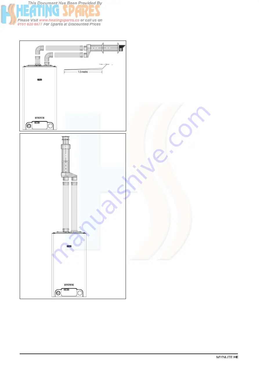
You must ensure that the entire flue system is
properly supported and connected.

Ensure that any horizontal sections of pipe have
a 1º fall towards the appliance (17mm per
1000mm).

Fig. 13

NOTE
It will be necessary to hold the valve with one
spanner whilst tightening with another.

4.6.1

GAS (fig. 6)
The appliance is supplied with a 15mm service
valve, connect a 15mm pipe to the inlet of the
valve and tighten both nuts.
NOTE
It will be necessary to calculate the diameter of
the gas supply pipe to ensure the appliance has
an adequate supply of gas.

4.6.2

FLOW & RETURN (fig. 6)
The appliance is supplied with 22mm service
valves for the flow and return connections, connect
a 22mm pipe to the inlet of each valve and tighten
both nuts.
NOTE
Depending on system requirements, it may
necessary to increase the size of the flow & return
pipe work after the service valve connections.

4.6.3

SAFETY VALVE (fig. 6)
Connect the safety valve connection pipe to the
safety valve outlet. Connect a discharge pipe to
the other end of the safety valve connection pipe
and tighten. The discharge pipe must have a
continuous fall away from the appliance to outside
and allow any water to drain away thereby
eliminating the possibility of freezing. The
discharge pipe must terminate in a position where
any water – possibly boiling – discharges safely
without causing damage or injury, but is still
visible.

4.6.4

CONDENSE PIPE
During normal operation the boiler produces
condense which is collected in a trap located in
the lower part of the boiler. A flexible pipe
(condense outlet pipe) is connected to the outlet
of the trap. The flexible pipe must be connected
to a plastic waste pipe only. The plastic waste
pipe must have a minimum of a 3º fall towards
the drain. Any external run of pipe should be
insulated to prevent the risk of freezing.

CONNECTING THE CONDENSATE OUTLET
Gently pull the condense outlet pipe down from
its location inside the boiler until approximately
100mm protrudes from the underside of the boiler.
Connect a suitable plastic (not copper) pipe (no
less than 20mm diameter) to the outlet pipe and
ensure it discharges in accordance with building
regulations or other rules in force.

4.7

ELECTRICAL CONNECTIONS
The electrical supply must be as specified in
section 3/3A. A qualified electrician should
connect the electrical supply to the appliance. If
controls – external to the appliance – are required,
a competent person must undertake the design
of any external electrical circuits, please refer to
section 8 for detailed instructions. ANY
EXTERNAL CONTROL OR WIRING MUST BE
SERVED FROM THE SAME ISOLATOR AS THAT
OF THE APPLIANCE. The supply cable from the

Fig. 12

Содержание Mynute 12HE

Страница 1: ...Supplied By www heating spares co Tel 0161 620 6677 Installation Servicing Instructions THESEINSTRUCTIONS TO BE RETAINED BY USER 0694 0694BR1207...

Страница 2: ...ombustion analysis 16 5 8 Final flushing of the heating system 17 5 9 Setting the boiler operating temperature 17 5 10 Setting the system design pressure 17 5 11 Regulating the central heating system...

Страница 3: ...pump expansion vessel safety val ve pressure gauge and automatic by pass The Mynute HE range are produced as room sealed category II2H3P appliances suitable for internal wall mounting applications on...

Страница 4: ...ector clockwise to increase the boiler outlet temperature or counter clockwise to reduce the outlet flow temperature 2 digit LED display Displays the current outlet temperature of the boiler During a...

Страница 5: ...Ignition is sensed by the electronic circuitry to ensure flame stability at the burner Once successful ignition has been achieved the electronic circuitry increases the gas rate to 75 of the MAX Heati...

Страница 6: ...l 12HE 15HE 20HE 25HE 30HE 35HE Power consumption Watts 150 150 150 150 165 165 Supply V Hz 230 50 Internal fuse 3 15A T for PCB 3 15A F for connections block External fuse 3A 2 8 Flue Details concent...

Страница 7: ...re to the side of the vertical terminal 500 mm Q From the top of the vertical terminal to the roof flashing As determined by the fixed collar of the vertical terminal 2 11 PUMP DUTY Fig 3 shows the fl...

Страница 8: ...ipes must be fitted in accordance with BS 6891 Pipe work from the meter to the appliance must be of adequate size Pipes of a smaller size than the appliance gas inlet connection must not be used The i...

Страница 9: ...ke up vessel or tank must be fitted with an approved non return valve andstopcockforisolationpurposes Thefeedpipe should be connected to the return pipe as close to the boiler as possible 3 6 8 FREQUE...

Страница 10: ...gard for the damage and discoloration thatmayoccurtobuildingproductslocatednearby The terminal must not be located in a place where it is likely to cause a nuisance see I S 813 In cold and or humid we...

Страница 11: ...by using a double pole switch with a contact separation of at least 3 5mm 3 high voltage category The switch must only supply the appli ance and its corresponding controls i e time clock room thermost...

Страница 12: ...top of the carton pull both sides open do not use a knife unfold the rest of the carton from aroundtheappliance carefullyremoveallprotec tive packaging from the appliance and lay the accessories etc t...

Страница 13: ...flue system Connect the required number of flue extensions or bends up to the maximum equivalent flue length to the flue terminal see fig 7 8 The flue system should have a minimum of 1 maximum of 3 r...

Страница 14: ...or additional bend s connect the required number of flue extensions or bends up to the maximum equivalent flue length between the boiler and vertical flue assembly see fig 8 Ensure that any horizonta...

Страница 15: ...level with or below that of the exhaust pipe Depending on site conditions it may be preferable to install the terminal assembly prior to fitting the twin flue pipes Mark and drill a level 130mm hole f...

Страница 16: ...ety valve connection pipe and tighten The discharge pipe must have a continuous fall away from the appliance to outside and allow any water to drain away thereby eliminating the possibility of freezin...

Страница 17: ...minal block When connecting the EARTH wire ensure that it s left slightly longer about 2cm that the others this will prevent strain on the EARTH wire should the cable become taut Do not remove the lin...

Страница 18: ...from the lowest points Open the drain valve full bore to remove any installation debris from the boiler prior to lighting Refill the boiler and heating system as described in 5 3 5 5 PRE OPERATION CHE...

Страница 19: ...urn valves until the individual return temperatures are correct and are approximately equal 5 12 FINAL CHECKS ENSURE ALL TEST NIPPLES ON THE APPLIANCE GAS VALVE ARE TIGHT AND CHECKED FOR SOUNDNESS ENS...

Страница 20: ...REPLACEMENT OF COMPONENTS Although it is anticipated that this appliance will give years of reliable trouble free service the life span of components will be determined by factors such as operating c...

Страница 21: ...return inlet pipe Disconnect thermistor electrical plug Replace in the reverse order 6 11 PRINTED CIRCUIT BOARD fig 21 Carry out component removal procedure as described in 6 4 Pull the control fascia...

Страница 22: ...eck and adjust burner pressure settings WARNING A GAS SOUNDNESS CHECK MUST BE CARRIED OUT 6 13 ELECTRODES CONDENSE SENSOR fig 23 Carry out component removal procedure as described in 6 4 Unclip and re...

Страница 23: ...flue collector E The heat exchanger can now be lifted up and withdrawn from the appliance 6 18 EXPANSION VESSEL fig 1 Should the removal and replacement of the expansion vessel be deemed impractical...

Страница 24: ...rols have been designed to further increase fuel economy by ensuring the boiler remains in the modulation phase during any heating requests This reduces the amount of ON OFF periods and therefore incr...

Страница 25: ...3 minute anti cycle has been performed and the temperature at the primary thermistor has dropped 5 C hysterisis below the set point NOTES When the request for heating and or hot water has been satisf...

Страница 26: ...and integrity Symptom Possible cause No display ignition Check wiring check electrical supply No hot water Check external controls No heating Check external controls Fault code Possible cause 10 Chec...

Страница 27: ...on of the fault These series of checks must be carried out before attempting any faultfinding procedures on the appliance On completion of any task that required the disconnection and re connection of...

Страница 28: ...circulation around heating circuit s thermistors flowsensor temperature AL34 Fan tacho signal fault Final Reset check appliance operation check fan AL40 Insufficient system water pressure Final Check...

Страница 29: ...re that these controls do not inhibit or limit the response to any heat request from a DHW cylinder Contact the controls manufacturer and orVokera technical department should you require more specific...

Страница 30: ...see photos 36 37 and connectthe230wiringharnessasindicatedinthe figs 39 40 The programmer can be used with a typical S Plan or Y Plan controls arrangement as detailed in figures 39 40 IMPORTANT The bo...

Страница 31: ...stor NTC AD01A Main PCB CN1 CN5 Connection to PCB 230V X2 X16 Connection to PCB 24V F O H T Flow over heat thermostat H E T Heat exchanger thermostat M3 M5 Terminal strip for supply in clock room ther...

Страница 32: ...Blue Green Yellow Room Thermostat Cylinder Thermostat Boiler programmer connections Boiler programmer connections Wiring Centre or Junction Box CylinderThermostat green yellow blue brown orange grey...

Страница 33: ...10028559 10028559 10028559 10028559 10028559 31 Case assembly 10028432 10028432 10028432 10028448 10028451 10028451 40 Door panel 10028553 10028553 10028553 10028553 10028553 10028553 78 Cover assembl...

Страница 34: ...005137 01005137 01005137 63 Pipe 10020898 10020898 10020898 10020898 10020898 10020898 200 Washer 5023 5023 5023 5023 5023 5023 265 Washer 5236 5236 5236 5236 5236 5236 266 Washer 5237 5237 5237 5237...

Страница 35: ...28539 10028539 10026272 10026272 71 Pipe 10028430 10028430 10028430 10028430 10028515 10028515 72 Venting plug 01005137 01005137 01005137 01005137 01005137 01005137 73 Cock 10028431 10028431 10028431...

Страница 36: ...28424 10028206 10028206 46 Gas diaphragm 10020265 10020265 10020265 10027161 10027162 10027162 67 Washer 10026322 10026322 10026322 10026322 10026322 10026322 69 Tryton 10028425 10028425 10028425 1002...

Страница 37: ...6323 482 Washer 10026366 10026366 10026366 10026366 10026366 10026366 487 Washer 10026345 10026345 10026345 10026345 10026345 10026345 509 High limit thermostat 10026982 10026982 10026982 10026982 100...

Страница 38: ...umgasrate 0 27 0 27 0 39 0 47 0 54 0 54 kg hr Injectorsize 3 6 3 6 3 6 4 7 5 0 5 0 mm Efficiency SEDBUK 93 3 92 9 92 6 92 4 92 8 92 9 Band A Band A Band A Band A Band A Band A Emissions CO max mg kWh...

Страница 39: ...r fan speed is not correctly adjusted according to the respective appliance specifica tion as detailed on the appliance data badge 10 7 1 CHECKING ADJUSTINGTHEAPPLIANCEFAN SPEEDS Move the selector swi...

Страница 40: ...DUCER BEEN FITTED YES NO WHAT TYPE OF SCALE REDUCER HAS BEEN FITTED FOR THE DOMESTIC HOT WATER MODE MEASURE RECORD GAS RATE 3 hr MAXIMUM BURNER OPERATING PRESSURE IF APPLICABLE mbar COLD WATER INLET T...

Страница 41: ...MPANY NAME TEL No CORGI ID CARD SERIAL No COMMENTS SIGNATURE SERVICE 3 DATE ENGINEER NAME COMPANY NAME TEL No CORGI ID CARD SERIAL No COMMENTS SIGNATURE SERVICE 4 DATE ENGINEER NAME COMPANY NAME TEL N...

Страница 42: ...Supplied By www heating spares co Tel 0161 620 6677...

Страница 43: ...Supplied By www heating spares co Tel 0161 620 6677...

Страница 44: ...General Enquiries Tel 0870 333 0520 Fax 01442 281403 After Sales Service Tel 0870 333 0220 Vok ra Ireland West Court Callan Co Kilkenny Tel 05677 55057 Fax 05677 55060 Vok ra Ltd reserve the right to...

Отзывы: