


05TA Service Manual
INSTALLING YOUR TUBE-ICE
®
MACHINE
7/19/13
3-5
Wiring and Electrical Connection
! WARNING !
Only service personnel experienced in refrigeration and qualified to work with high voltage
electrical equipment should be allowed to install or work on the Tube-Ice
®
machine.
! WARNING !
Refer to TABLE 3-2 below to properly size wiring connections. A fused disconnect must be
provided near the Tube-Ice
®
machine. Connect 3 phase power to the power distribution block (PDB)
for operation of the Tube-Ice
®
machine and its controls. Rotation checking of cutter motor and water
pump is required (see following section). Also, if one leg of the 3 phase power is higher or lower
(“Wild”), then it should be connected to terminal #L2. Connect the “Ground” wire to the “Ground”
lug provided.
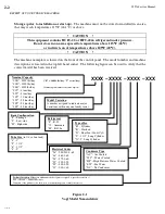
FIGURE 3-3
Control Panel Power Connections
Water Cooled
Air Cooled
Standard Voltages
F.L.A.
Min. Ampacity Max. Fuse
F.L.A.
Min. Ampacity Max. Fuse
208/230, 3ph, 60 Hz
66.9
81.8
145
80.9
95.8
160
460, 3ph, 60 Hz
32.7
39.9
70
39.7
46.9
80
220, 3ph, 50 Hz
67.5
82.4
145
81.5
95.8
160
400, 3ph, 50 Hz
33.2
40.4
70
40.2
47.4
80
TABLE 3-2
Electrical Specifications
AUX CONNECTIONS
Cutter Motor, Pump Motor
& Compressor Interlocks
MAIN MACHINE POWER
Incoming power to be connected to
Power Distribution Block (PDB)
AIR COOLED CONDENSER
CONNTECTIONS
Power for Fan Motors (B7, B8 & B9)
AIR COOLED CONDENSER CONNTECTIONS
Power for Condenser control circuit (11 & 22)
Содержание P118F/HE100
Страница 4: ...Vogt Tube Ice Machines Installation Service Manual and Parts Catalog 12A4171M06 05TA Model ...
Страница 10: ...05TA Service Manual TABLE OF CONTENTS vi ...
Страница 20: ...05TA Service Manual INTRODUCTION 7 19 13 1 10 ...
Страница 40: ...05TA Service Manual INSTALLING YOUR TUBE ICE MACHINE 3 7 14 3 18 BLANK PAGE ...
Страница 50: ...5 6 5TA Service Manual START UP AND OPERATION 7 19 13 Blank page ...
Страница 52: ...05TA Service Manual ELECTRICAL CONTROLS 3 10 14 6 2 FIGURE 6 2 Control Panel Components Standard ...
Страница 57: ...05TA Service Manual ELECTRICAL CONTROLS 3 10 14 6 7 FIGURE 6 3 Electrical Schematic All Voltages 50 60 Hz ...
Страница 106: ...05TA Service Manual SERVICE OPERATIONS 3 10 14 9 28 Blank ...
Страница 113: ...05TA Service Manual 10 7 OPTIONS AND ACCESSORIES FIGURE 10 4 Wiring Schematic Mid Size Machine P112 P118 P18XT ...
Страница 114: ...Blank page ...
Страница 115: ...05TA Service Manual TABLES CHARTS 3 10 14 11 1 11 Tables Charts ...
Страница 126: ...05TA Service Manual INDEX 4 15 14 12 4 ...