background image

APPLICATION

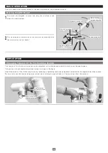
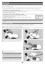
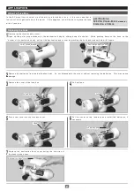
A commercially available USB external battery with USB micro-B connector is needed.  

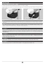
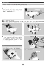
Connect the USB external battery to the external power supply port of the R.A motor module with a USB micro-B connecter cable as 
shown in the figure.

Using a USB External Power Supply

Note 1: 

The USB external battery will take priority over the AA batteries if you turn on the power while the AA batteries remain in the battery 

compartment. 

Note 2: 

If the USB external battery is exhausted (its voltage power is dropped), the display on the STAR BOOK ONE begins blinking.  If this 
happens, exchange the USB external battery for new ones (or fully recharged ones).

Be sure to turn off the power when you remove the USB external battery while the AA batteries remain in the battery 
compartment.  Although this does not lead to damage, it may cause an operation error or initialize your settings on the 
STAR BOOK ONE.

Caution 1 : 

When you unplug the power cable, be sure to hold the connector part and pull it straight.  Unplugging by grabbing the 
cable part may cause a wire to snap. 

Caution 2 : 

Avoid pulling or bending a part of the power cable adjacent to the connectors.  It may cause a wire to snap.

Caution 3 : 

Do not use the power cable in a folded and tied condition.  It may cause electrical shock or fire.

Caution 4 : 

External power supply port 

(USB Micro-B: 5V)

USB Micro-B 

connector cable

External power supply port 

(USB Micro-B: 5V)

USB Micro-B 

connector cable

15

Содержание APZ

Страница 1: ...Instruction Manual for Altazimuth Mount...

Страница 2: ...is could result in fire or electrical shock Make sure to be safe and consult your local Vixen dealer or distributor in your country Do not allow liquids or foreign objects to enter the product Unplug...

Страница 3: ...ncing the APZ Mount BASIC OPERATION Moving the APZ Mount APPLICATION Changing the Tension of the Friction Stop Motion About Power Supply AP Mount Composition Chart Variations on the APZ Mount How to C...

Страница 4: ...well balanced after your accessories have been installed 3 Be careful not to bang any part of the mount against other objects This could damage the gears and bearings Package Contents Basics of the AP...

Страница 5: ...e Prism Diagonal Drawtube Focus Knob Ferrule with protection rubber Lens Shade Objective Lens inside Safety Screw Leg Brace Lock Screw Dovetail Tube Plate APP TL130 Tripod Leg Brace Extension Lock Lev...

Страница 6: ...large grab knob and safety screw This allows quick set up and removal of the optical tube AZ Counterweight The optical tube mounted on the APZ mount has to be balanced with the AZ counterweight to mak...

Страница 7: ...pulling it out so that the tripod leg can be adjusted To keep the better stability extend the upper section of the tripod legs at first Pull out the tripod legs until each leg extends to your necessar...

Страница 8: ...other hand so that the top of the column fits in the bottom of the mount Turn the center column counterclockwise to screw the top of the column into the bottom of the mount until securely fastened Pus...

Страница 9: ...tions of the tip on the shaft Slow motion control knob Manual slow motor control module Manual slow motor control module Flat portion of the socket Flat portion of the socket Flat portion of the socke...

Страница 10: ...e dovetail tube plate Make sure that the dovetail tube plate is flat against the mount head Tightening the dovetail plate lock screws with a gap between these parts may cause the telescope tube to fal...

Страница 11: ...elease the telescope tube to see if it keeps the position as it stands Readjust the balance if the telescope tube starts turning as you release it Loosen the lock knobs on the tube rings that hold the...

Страница 12: ...screw and safety screw on the mount head that hold the telescope s dovetail slide bar and slide the dovetail slide bar either forward or backward until the telescope tube remains stationary Tighten th...

Страница 13: ...n the figure Adjust the tension of the friction stop motion by loosening or tightening the tension adjustment screws with the supplied 4mm Allen wrench Be sure to loosen the tension adjustment screw w...

Страница 14: ...nts if you use an external power source such as a USB external mobile battery for the APZ mount Power supply to the R A motor module only The USB external power supply battery of 0 5 ampere and more i...

Страница 15: ...ew ones or fully recharged ones Be sure to turn off the power when you remove the USB external battery while the AA batteries remain in the battery compartment Although this does not lead to damage it...

Страница 16: ...Unit AP Mounting Base Post DEC Motor Module R A Motor Module APZ Mount Composition Chart SXG or APP TL Tripod Mount Head Base STAR BOOK ONE Controller APPLICATION Modules for the APZ Mount The APZ mo...

Страница 17: ...ime lapse Photography Consisting of APZ Mount Unit Counterweight Bar Unit with vanity ring AP Polar Axis Body Unit Consisting of APZ Mount Unit R A Motor Module with STAR BOOK ONE Set Dovetail Slide B...

Страница 18: ...3 How to Change the Modules Example 1 Changing the APZ Altazimuth Mount into the AP Equatorial Mount with manual slow motion controls Remove the optical tube counterweight bar and controller before c...

Страница 19: ...in one hand to prevent it from turning together with the center column 5 Attach the metal post on the tripod head The metal post is underneath the center column Be sure to screw down the metal post co...

Страница 20: ...ews Position the mount base of the AP polar axis body unit so that the two azimuth adjustment screws come above the metal post Place the mount base so that the center projection on the bottom of the m...

Страница 21: ...it so that the electrical contact on the declination body fits into the sunken portion on the manual slow motion control module Rotate the manual slow motion control module so that the screw holes lar...

Страница 22: ...ation body cover with attention to the direction of the hook on the cover Screw the threaded end of the counterweight bar into the threaded hole on the conical vanity ring After you fully tighten the...

Страница 23: ...put through the counterweight At this stage the counterweight should be close to the upper end of the counterweight bar to bring the center of balance near to the mount Tighten the lock knob on the co...

Страница 24: ...module Loosen the two socket head cap screws on the declination body with the 4mm Allen wrench as shown in the figure Remove the declination body assembly including the manual slow motion control mod...

Страница 25: ...s in place and tighten the screws securely with the 3mm Allen wrench Attach the R A motor module onto the AP mounting base post so that the electrical contact faces to the outside as shown in the figu...

Страница 26: ...nstall the batteries if necessary Tighten the screws securely with the 4mm Allen wrench Replace the declination body cover with attention to the direction of the hook on the cover Declination body Dec...

Страница 27: ...e the cover of the fuse box Remove the batteries from the declination body Do not disassemble the mount without removing the batteries This may cause damage About a Fuse Box pecifications 125V 1A Clas...

Страница 28: ...ear Azimuth 58 4mm in diameter 144 tooth wheel gear Altitude 11 0mm in diameter Brass Azimuth 9 8mm in diameter Brass 59mm in diameter Aluminum alloy with friction stop mechanism 59mm in diameter Alum...

Страница 29: ...djustable from 526mm 20 7 to 1159mm 45 6 L e n g t h a d j u s t a b l e f r o m 5 7 0 m m 2 2 4 t o 1 2 9 6 m m 5 1 0 78mm 3 07 80 5mm 3 17 38 5mm 1 52 Worm gear shaft The specifications are subject...

Страница 30: ...Memo 30...

Страница 31: ...Memo 31...

Страница 32: ...63 7 0 5S 314 Miz M 5 17 3 Higashitokorozawa Tokorozawa Saitama359 0021 Japan P h o n e 81 4 2944 4141 International F a x 81 4 2944 9722 International http www vixen co j p...

Отзывы: