


8
LOCATION OF SERVICES
All services must be accessible for installation
and service. Ensure all services are kept within 40”
of the V3-201 and V3-202 Dispensing Systems.
Water Shutoff Valve to be located at low level.
Ensure there is sufficient room for a 6” long fitting to
be connected to the Water Shutoff Valve.
Top of drain should be located between 12” and
18” from floor level.
SHIPPING DAMAGE/MISSING PARTS
Unpack and inspect the unit for shipping damage
and/or missing parts. If any damage or missing
parts are found, contact
Vivreau Service
Toll-
Free at 877-999-1044 and report the missing or
damaged parts.
INSTALLER’S CHECKLIST
Below are the services required to be in place
prior to the installation of the Vivreau Dispensing
System. Please review and check all services
before beginning work. If anything is missing or not
correct, do not start the installation. Call
Vivreau
Service
for instructions at 877-999-1044.
WATER SUPPLY
A potable 1/2” cold water supply terminating in a
1/2” Ball Valve, 1/2” female pipe thread.
IMPORTANT ________________________
Ball Valve must be accessible for service and
installation.
Any water line or valve less than 1/2” is not
acceptable. Must be a direct supply with no
other Inline Filters.
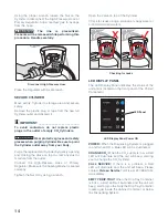
ELECTRICAL OUTLET(S)
All Electrical Outlets must be within 40” of unit. No
Extension Cords.
Model V3-201 and V3-202
(1) 20 Amp Electrical Circuit (NEMA 5-20R) 120V,
60 Hz (11 Amps)
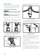
CO
2
CO
2
Cylinder (Customer supplied) must fit within
the allotted space.
CO
2
Cylinder must always remain vertical.
If connecting to a bulk or existing CO
2
system, a
CO
2
line terminating at a 1/4” Barbed Shutoff Valve
must be available within 40” of the unit with 100
PSI minimum pressure.
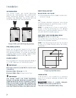
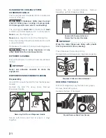
DRIP TRAY AND DISPENSING HEAD
CUTOUTS
For under-counter units, cut out the holes for the
Drip Tray and Dispensing Head per the template.
The Dispensing Head must be mounted on the
work surface directly above the Chiller/Carbonator.
The Dispensing Head lines must never be
extended.
DRIP TRAY DRAIN (OPTIONAL)
Drip Tray can be plumbed to a drain. Customer will
need to supply a properly trapped drain according
to Federal, State and Local Codes. The drain must
be large enough to accommodate a 1” OD flexible
pipe.
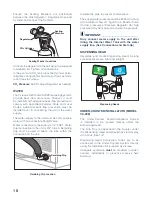
VENTILATION
If the system is to be installed in an enclosed
space or in a cabinet, adequate ventilation must
be provided.
In lieu of a Stand-Pipe Drain, the Internal Drip Tray
Container may be used.
CAUTION
Failure to provide adequate
ventilation will cause system failure.
This unit is to be installed indoors only.
Содержание V3-202
Страница 1: ...1 V3 201 and 202 Dispensing Systems Service Manual ...
Страница 41: ...41 ...