background image

EN - 11

English

Based on the live image retrieved from the camera, adjust the camera lens by doing the 
following:

W

T

8

N

DO NOT over tighten the controllers. 
Doing so would damage the structure 
of camera lens.

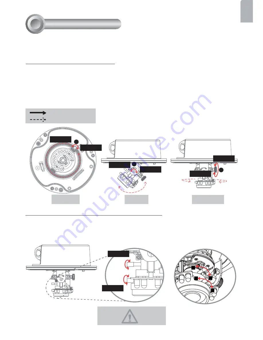
To adjust the viewing angle

1. Loosen the pan screw and then turn the lens module left and right. Upon completion, 

tighten the pan screw.

2. Loosen the tilt screws on both side of the camera and then turn the lens module up and 

down. Upon completion, tighten the tilt screws.

3. Loosen the image adjustment screw and then turn the lens to adjust the image 

orientation. Upon completion, tighten the image adjustment screw.

To adjust the zoom factor and focus range

1. Loosen the zoom controller and then adjust zoom factor by moving the controller left and 

right. Upon completion, tighten the zoom controller.

2. Loosen the focus controller and then adjust focus range by moving the controller left and 

right. Upon completion, tighten the focus controller.

3

1

2

Loosen

Tighten

Loosen

Tighten

Loosen

Tighten

Loosen

Tighten

Rotate the screw

Turn the lens

Adjusting the Lens 

7

Pan 350°

Tilt 95°

Rotate 350°

Содержание FD7141

Страница 1: ...FD7141 V...

Страница 2: ...utor when such cases happen Refer to your user s manual for the operating temperature Warning Before Install Do not place the Network Camera on unsteady surfaces Do not touch the Network Camera when i...

Страница 3: ...sticker Ceiling hole template sticker Alignment Sticker Drill hole At least drill 2 pilot holes symmetrically on each side to avoid falling Bottom base Plastic cover FD7141V only Power adapter Package...

Страница 4: ...ent screw Status LED Light sensor Physical Description 2 Pan screw Lens Inner View Ethernet 10 100 RJ45 plug Audio out green Microphone in pink Power cord socket black General I O terminal block Earth...

Страница 5: ...s subject to the following two conditions 1 This device may not cause harmful interference and 2 this device must accept any interference received including interference that may cause undesired opera...

Страница 6: ...holes symmetrically on each side into the ceiling Then hammer the supplied four plastic anchors into the holes 3 Through four holes on the bottom base insert the supplied four screws to corresponding...

Страница 7: ...the holes 3 Through four holes on the bottom base insert the supplied four screws to corresponding holes and secure the bottom base with a screwdriver 4 Feed the cables through hole A or B If you wan...

Страница 8: ...or N C No Connector N C No Connector AC24V Power in AC 24V AC24V Power in AC 24V G N D Ground D I Digital Input D O Digital Output 12V Power 12V DC GND DI DO 12V Ceiling mount without the bottom base...

Страница 9: ...When using a non PoE switch Use a PoE power injector optional to connect between the Network Camera and a non PoE switch When using a PoE enabled switch The Network Camera is PoE compliant allowing tr...

Страница 10: ...83236 1 Install the Installation Wizard 2 under the Software Utility directory from software CD 2 The program will conduct analyses on your network environment After your network is analyzed please cl...

Страница 11: ...N 10 For further setup please refer to user s manual on the software CD Ready to Use 6 1 Access to the Network Camera from the Internet 2 Retrieve live video through web browsers or recording software...

Страница 12: ...etion tighten the tilt screws 3 Loosen the image adjustment screw and then turn the lens to adjust the image orientation Upon completion tighten the image adjustment screw To adjust the zoom factor an...

Страница 13: ...e supplied screwdriver Finally make sure all parts of the camera are securely installed Completion 8 Note If you use FD7141V f 9 22 mm please hold the supplied plastic cover in front of the lens while...

Страница 14: ......

Отзывы: