


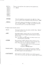


3. Electrical
conditions
a) Signal
levels
All
input/output
signals
are
TTL
level.
“HIGH”
level
42.4
5.0[V]
At
the
receiving
pin
“LOW”
level
+0.0
0.4[V]
on
printer
side.
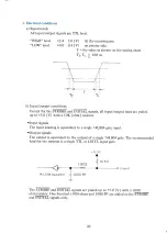
T
=
the
value
as
shown
on
the
timing
chart.
Ts, T,
<
100
ns
b)
Input/output
conditions
Except
for
the
STROBE
and
INITIAL
signals,
all
input/output
lines
are
pulled
up
to
+5.0
[V]
with
a
1OK
[ohm]
resistor.
"Input
signals
The
input
loading
is
equivalent
to
a
single
74LS04
gate
input.
"Output
signals
The
output
is
equivalent
to
the
output
of
a
single
74LS04
gate.
The
recommended
load
for
the
outputs
is
a
single
TTL
or
LSTTL
input
gate.
100Q
linput]
74
LS
04
equvalent
1000
PF
L
The
STROBE
and
INITIAL
signals
are
pulled
up
to
+5.0
[V]
with
a
1000
ohm
resistor.
One
hundred
(100)
ohms
and
1000
PF
are
added
to
the
STROBE
and
INITIAL
signals only.
20
Содержание Transtar 315
Страница 1: ...Tran Star 315 Color Graphics Printer Operator s Manual ...
Страница 3: ...Transtar 315 Color Graphics Printer Operators Manual ...
Страница 9: ...Parts of the Printer i _ Upper case A Paper feed Figure Printer cover ...
Страница 12: ..._ Part 2 Installation Use ...
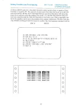
Страница 47: ...Dot Graphics Example 7 10 REM EXAMPLE GRAPHICS 20 LPRINT CHR 27 KOO1 CHR 75 30 LPRINT OO2 00 0 42 O LO LO ...