background image


Product Information  

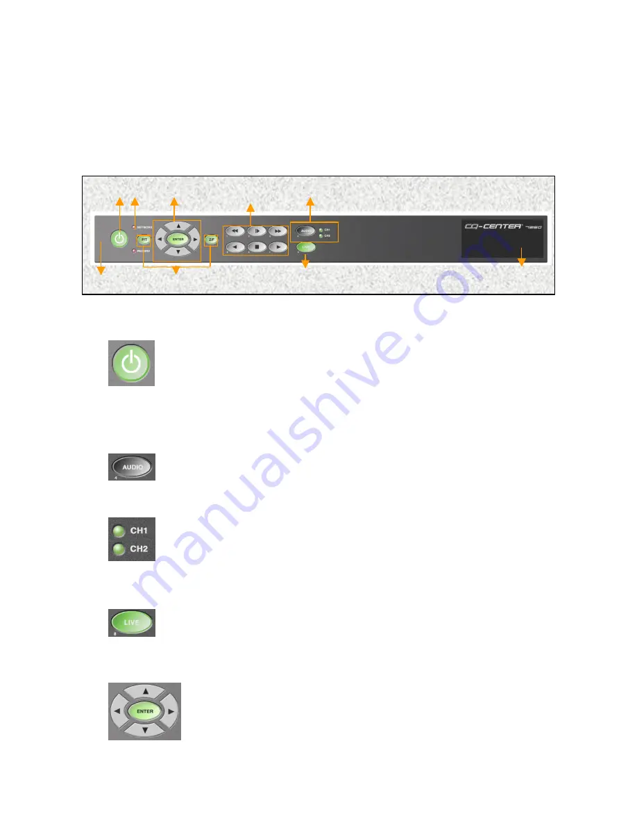
1.  Front Panel 

The Audio button is used to select the desired audio channel.  By
pressing  this button, the user will scroll through CH1, CH2, and MUTE.  
Select the desired audio channel for playing back recorded audio. 

1.  Power 

2.  Audio Selector 

Power On/Off Button.  Power Off is indicated by RED and Power On 
status is indicated by GREEN.  To turn the system on, press the Power 
key.  The key should turn amber.  Enter the password (default is 1111) 
using the remote control and press the power key again.  The key should  
The key should turn green and the system should become active.  To turn 
the system off, repeat the above step. 

The Green light Indicates the selected audio channel.  When both 
indicators are not illuminated, this signifies MUTE status. 

3.  Video Selector 

The Green LIVE button indicates that the system is in the live viewing 
mode.  This button is also used to return the system to live viewing
mode from the playback mode. 

When in live mode, the user can select a screen to be viewed as a 
single, full screen.  A channel can be selected by using the directional 
key *(the channel number will be illuminated in yellow).  Once selected, 
the user can view the channel full screen by pressing the ENTER key. 
To return to the quad m


ode, press the ENTER key again. 

4


Содержание VT-DVR04

Страница 1: ...VT DVR04 4 CHANNEL DIGITAL VIDEO RECORDER User s Manual Version 2 1 ...

Страница 2: ...ternal Sensor In 7 RS 485 Terminal P T Z F 7 Remote Control 8 Using the Remote Control 9 Remote Control Functions 10 Power On Off 10 Event Log Display 10 OSD On Screen Display On Off 10 M D motion detection Area Display On Off 10 Network Status 10 Sensor Off 10 Alarm On Off 10 Video Screen Selector 10 Audio Selector 11 Playback Controls 11 Directional and Enter Keys 11 Menu 11 Exit Live 11 P T and...

Страница 3: ... This unique feature allows the user to use this technologically complex system without prior knowledge of operating a computer system VT DVR04 is a state of the art DVR security system that can be monitored from anywhere in the world through a Network Interface Card NIC and a DSL or secured line Safety and Precautions 1 Only use the power source provided with the product 2 Do not block the vent a...

Страница 4: ...on 1 Components o VT DVR04 main component o Remote Control batteries included o Power Cable o User s Manual o Warranty Card o Software Diskettes Set of 2 o Rack Mount Bracket Getting Started 1 Remote control uses two AAA batteries 2 Battery life depends on usage 3 Please keep extra batteries handy for future use NOTE 3 ...

Страница 5: ...e key should turn green and the system should become active To turn the system off repeat the above step The Green light Indicates the selected audio channel When both indicators are not illuminated this signifies MUTE status 3 Video Selector The Green LIVE button indicates that the system is in the live viewing mode This button is also used to return the system to live viewing mode from the playb...

Страница 6: ...egin to blink Select the desired time by pressing the up or down cursor Press the right or left cursor to skip to the next digit then press the PLAY button When lit the light indicates that system is currently recording 7 P T Z F Control If the system is connected to a P T Z camera the camera can be controlled from the system From the live single screen mode press the P T or the Z F button Camera ...

Страница 7: ... Switch Monitor Up to Four cameras can be programmed to switch sequentially Main Monitor Live and Playback is shown with the On Screen Display OSD CANNOT BE USED SIMULTANEOUSLY WITH OPTIONAL COMPUTER MONITOR CRT OUTPUT Multiplex Output Four screens are shown without OSD Main Monitor Secondary Option User can view the Live and Playback screens through a computer monitor CANNOT BE USED SIMULTANEOUSL...

Страница 8: ... port for remote access 8 External Remote Control Sensor Terminal 9 External Alarm Out 12V and 5V output can be selected and can be connected to an external alarm system Normal Low 10 External Sensor In Up to four Open Close Relay type Sensors can be connected to the system 11 RS 485 Terminal P T Z F For use with IR repeater if unit is located in a remote area equipment closet ETC Direct connectio...

Страница 9: ...s Indicator 6 Sensor Off S1 S2 7 Alarm On Off 8 Video Selector 9 Audio Selector 10 Playback Controls 11 Directional keys and Enter 12 Menu 13 Exit 14 P T Z F 15 VISS Set Find 16 Remote Control ID Selector 17 HELP software firmware version 3 Remote Control 1 2 3 6 7 4 5 9 12 14 16 17 10 8 11 13 15 14 8 ...

Страница 10: ... feet away at angles not exceeding 60 degrees from the VT DVR04 IR transmitter is located at the center of the remote control and should face the VT DVR04 2 VISS SET FIND The VISS SET FIND Button on the remote control allows the user to bookmark a given incident during playback and automatically return to that incident 3 Keypad Another prominent feature of the VT DVR04 is the keypad located on the...

Страница 11: ...layed user can select an event with the directional keys and when the ENTER button is pressed the system will playback that selected event NOTE Event log is only possible when The system is set to Event Recording 3 OSD On Screen Display On Off 4 M D motion detection Area Display On Off 5 Network Status Indicates the network status of the system If there is an unwanted network intrusion user can ma...

Страница 12: ...he previous screen when in the Menu mode Used to go back to Live View mode from the Playback mode 14 P T and Z F 15 VISS Find Set This is the system s video bookmark Up to five marks can be set for quick review By Pressing the VISS set the user can mark the beginning of a desired footage By pressing find the user can view the marked footage 16 R C remote control SET In cases where there are multip...

Страница 13: ...ll time may be set individually from 1 to 9 seconds between cameras The Spot Monitor output is located in the rear of the unit 8 Motion Detection Use to set sensitivity and area of detection for each individual camera There are 3 sensitivity levels Minimum Use primarily for outdoor cameras to avoid false events Default is the center setting use for most applications Max use for confined areas with...

Страница 14: ...imity Color Tune Each camera can be adjusted individually for brightness contrast saturation and hue Camera Name Change the On Screen Display OSD camera title Press enter to select camera Move box to desired characters and press enter Use the to erase characters Main Monitor Use to select main monitor output as computer CRT or composite TV After selecting you must reboot the system for it to recog...

Страница 15: ...nd inactivate it 4 The screen is not clear o The displayed images and the images that were compressed and restored are programmed to be of the same quality If you are not satisfied with the display please refer to the Setting Video Color section of the Configuration chapter of the User s Guide and manipulate the display o If you still feel that there is a significant difference please recalibrate ...

Страница 16: ...9970 GLENOAKS BLVD UNIT B SUN VALLEY CA 91352 PHONE 888 VITEK 70 818 771 0300 FAX 818 771 0400 WWW VITEKCCTV COM ...

Отзывы: