1 March, 2005
V1642OM.DOC
Page 9 of 9
3.6 FADE
TO
BLACK
The V1642 includes a fade to black facility. This enables the output to be cleanly attenuated to digital
black on receipt of an external command.
The rate of the fade is fixed at half a second.
The fade can be initiated through either of the remote control systems or electrically by closing contacts.
By using the remote systems it is easy to see whether the unit’s output has been faded down or not, but
this is harder with external control.
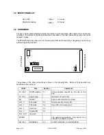
A D-type connector on the rear panel is used to initiate a fade from an external system. The
connections are given in section 2.1. There is an internal pull-up resistor (1.1K
Ω
) so the external
system needs only to short circuit the two contact together to initiate a fade. Some early rear panels
only had one D-type connector, but two extra BNCs. In this case use either BNC (they are connected in
parallel for a looping reference on some modules) and simply short the core to the screen.
The actual fade is initiated by a falling edge on the control signal. Some hysteresis is applied to the
detection for noise immunity, so there is a minimal delay.
The output will stay at black until the control signal is released, or at least brought back to a logic HIGH.
There is no indication on the unit itself that a Fade to Black has been completed. So, after a reset,
either automatically after power up or manually after pressing S6, the unit will not be faded down.
However it will still have all the other settings from before the reset.
3.7 RS485
CONFIGURATION
RS485 provides a simple means of multi-drop control of up to 64 units from a PC. Since most PCs only
have RS232 comms ports it is usually necessary to interface through a ‘RS232 to RS422’ converter.
(RS422 and RS485 are identical from an electrical viewpoint for this conversion.)
Since RS485 is multi-drop it is necessary to set a unique address on each unit connected to it. DIL
switch S1 bits 0 (LSB) to 5 (MSB) inclusive set the address in the range 0 to 63. Each switch set to ON
represents a logic 0, so for example an address of 05 will be set by
X
X OFF OFF OFF ON OFF ON
The address set on S1 is only read by the unit when the processor is reset, either automatically after
power up or manually on S6.
It is possible to set the communications to RS232 by moving all the switches in S9 to their OFF position.
RS 232 is only point to point but it does offer simpler control if a PC is connected to only one unit. In this
case the address is not so important, but Iitis still read by the software.
3.8 FACTORY
INITIALISATION
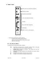
The front panel can only show the status of one of the four parameters, unless the operator rotates the
selection switch through each one. This is laborious to set everything back to CAL. Thus if the
σ
and
τ
buttons are held down simultaneously for at least
5
seconds, then all parameters will be reset. Clearly
any link settings will not be affected.
For about a second all the central LEDs will be ON to show that the initialisation has been completed.


