


Page 6 of 9
V1642OM.DOC
17 February, 2005
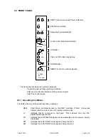
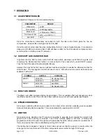
2.5.2 Adjustments
The central section is used in Local control to select which of the four available parameters is to be
adjusted and to make the adjustment. Three parameters are always available, while the fourth depends
on the signal format. Once a parameter has been selected then it is changed by pressing the
σ
and
τ
buttons.
Any adjustment can be returned to its calibrated value by pressing the
σ
and
τ
buttons simultaneously
for at least half a second.
The three central LEDs give an indication of the parameter status. The green CAL lamp is ON if the
parameter is in its default, calibrated position, while the two amber LEDs indicate if it is above or below.
For the De-Hanover Bar the CAL LED will be ON when it is not selected, and the upper green LED will
be ON otherwise.
2.5.3 Control Source
The lowest switch has three positions and selects the control source:
Rem
Control is from the DART system. This requires the use of an external
controller running a suitable programme, which communicates with multiple
racks using the Dartnet protocol.
RS485 Control is over an RS485 multi-drop network using a simple protocol and
connecting to the unit via a 9 way D type connector on the rear module. The
details of this protocol are freely available and are published as an addendum
to this manual.
Local
Control is from the front panel itself.
2.6 INITIALISATION
When the unit powers up or has been manually reset by pressing S6 then the on board controller needs
to initialise certain circuitry. This takes a few seconds during which there is no output, but it is indicated
on the front panel by short regular blips on the green CAL LED. The other LEDs, except for +V and
REM, are OFF during initialisation. The end of initialisation is shown by normal displays on the front
panel and a D1 output, provided an input is present.
When the unit powers up it will be reset to same conditions as when power was removed until it is
changed. In either of the Remote control modes any changes will be made by the control system, but in
Local they will be made on the front panel.
The settings are not stored immediately after they are changed, but at irregular intervals, such as after a
short time interval following a change with no further changes. This is done to reduce the number of
storage operations when the panel is being worked hard. However it does mean that the most recent
changes made immediately before a power down may not be stored.
2.7 ANCILLARY
DATA
AND
VERTICAL
INTERVAL
The V1642 passes all ancillary data and all data in the active portion of the vertical interval unmodified.
Thus all audio or Teletext or VITS is unaffected by the processing.
2.8 TRS
SIGNALS
The V1642 passes the TRS signals from the input signal through to the output without regeneration.
Thus any erroneous TRS on the input will also appear at the output.
2.9 EDH


