


1 March, 2005
V1642OM.DOC
Page 5 of 9
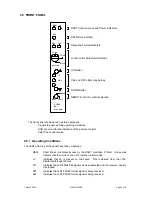
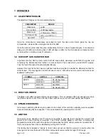
2.5 FRONT
PANEL
REM
+V
Local
Rem
V1642
SDI
Proc. Amp.
CAL
+
-
DART Control Access and Power indicators
Operating Format Indicators
Local Control Parameter Selection
UP Button
CAL and OFF LEDs (see below)
DOWN Button
REMOTE / LOCAL control selection
RS485
VGain
CGain
Black
DeH/Hue
270
525
625
SDI Format Indicator
The front panel shown above has three purposes:
Provide the user with the operating conditions
Offer Local control and indication of the primary controls
Select the control source
2.5.1 Operating Conditions
The LEDs at the top of the panel have these meanings
REM
Short blinks to indicate access by the DART controller, if fitted. It does
not
indicate that the unit is in one of its remote control modes.
+V
Indicates that 5V is present on the board. This is derived from the +15V
distributed through the rack.
270
Indicates that a 270MHz SDI signal has been detected and the receiver circuitry
has locked.
525
Indicates that a D1 525/60 format signal is being received.
625
Indicates that a D1 625/50 format signal is being received.


