background image


11. OVERLOADING     

Do not overload wall outlets and extension cords as this can result in a risk of fire or 
electric shock. 

12. SERVICING        

 Do not attempt to service the video monitor or equipment yourself as opening or 
removing covers may expose you to dangerous voltage or other hazards.   


Refer all servicing to qualified service personnel. 

13. DAMAGE REQUIRING SERVICE 

Unplug the equipment from the wall outlet and refer servicing to qualified service 
personnel under the Following conditions: 


A.

 When the power supply cord or the plug has been damaged.       


B.

 If liquid has spilled or objects have fallen into the Unit.       

      C.

 If the equipment has been exposed to water or other liquids. 

D.

 If the equipment does not operate normally by following the operating  

instructions, adjust those controls that are covered by the operating instructions as  
Improper adjustment for other controls may result in damage to the unit.   


E.

 If the equipment has been dropped or the casing is damaged.       


F.

 When the equipment exhibits a distinct change in performance.    

14. REPLACEMENT PARTS       

When replacement parts are required, be sure the service technician uses 
replacement parts specified by the manufacturer or that have the same 
characteristics as the original part. 

      Unauthorized substitutions may result in fire, electric shock, or other hazards. 

15. SAFETY CHECK 

Upon completion of any service or repairs to the equipment, ask the service 
technician to perform safety checks to verify that the equipment is in proper 
operating condition. 

16. FIELD INSTALLATION 

The installation of equipment should be made by a qualified service person and 
should conform to all local codes. 

17. CAUTION - THESE SERVICING        

      INSTRUCTIONS ARE FOR USE BY QUALIFIED SERVICE PERSONNEL ONLY.  

TO REDUCE THE RISK OF ELECTRIC SHOCK DO NOT PERFORM ANY 
SERVICING OTHER THAN THAT CONTAINED IN THE OPERATING 
INSTRUCTIONS UNLESS YOU ARE QUALIFIED TO DO SO. 

18.

 Use certified/Listed Class 2 power supply transformer only


Содержание ProtosV 580/4

Страница 1: ...ProtosV 580 4 Installation Manual Set up and user manual for the VPC580 4CM VPC580 4DN VPC580 4WDR Cameras ...

Страница 2: ......

Страница 3: ...erating maintaining and troubleshooting this product refer to this document and any other documentation provided If you still have questions please contact Norbain Technical Support and Sales Norbain SD Ltd 210 Wharfedale Road Winnersh Triangle Wokingham Berks RG41 5TP 0118 912 5000 Note You should be at the equipment and ready with details before calling Technical Support Conventions Used in this...

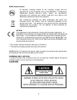
Страница 4: ...dance with the following EU standards has been made The manufacturer declares that the product supplied with this document is compliant the provisions of the EMC Directive 89 336 EEC the Low Voltage Directive LVD 73 23 the CE Marking Directive 93 68 EEC and all associated amendments This symbol indicates electrical warnings and cautions This symbol indicates general warnings and cautions NORBAIN S...

Страница 5: ...n the marking label If you are not sure of the type of power supplied at the installation location contact your dealer For equipment designed to operate from battery power refer to the operating instructions 8 GROUNDING OR POLARIZATION Equipment that is powered through a polarized plug a plug with one blade wider than the other will fit into the power outlet only one way This is a safety feature I...

Страница 6: ...may result in damage to the unit E If the equipment has been dropped or the casing is damaged F When the equipment exhibits a distinct change in performance 14 REPLACEMENT PARTS When replacement parts are required be sure the service technician uses replacement parts specified by the manufacturer or that have the same characteristics as the original part Unauthorized substitutions may result in fi...

Страница 7: ...7 TABLE OF CONTENTS INTRODUCTION 8 CAMERA OVERVIEW 9 CONTENTS OF PACKAGE 10 CAMERA ADJUSTMENT 10 CONTROL AND CONNECTIONS DAY NIGHT I O TERMINALS 15 LENS 16 SPECIFICATIONS 17 ...

Страница 8: ...er 1 50 1 100 000 and manual electronic shutter modes OSD On Screen Display Auto and manual white balance modes Selectable BLC Zone 16no Privacy Zones 4no Motion Detection MD areas that activate an alarm output 0 5v TTL Mirror D Zoom Nega Posi Sharpness D N B W V Flip Rotation Freeze AGC Auto Gain Control RS485 Control Internal AC line lock Compatible with video or DC type lenses with OSD select Q...

Страница 9: ...on Up Button Enter Button Right Button Down Button UTP Video Output Day Night External I O Motion ALARM OUT RS 485 Power Indicator Video Out Connector BNC UTP BNC Selection Switch WDR only AC DC Compatible Input Terminal AC Power Cord Terminal Block REAR VIEW ...

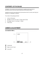
Страница 10: ... remove the colour camera and its accessories from the carton and verify that they were not damaged in shipment The content of the package includes 1 Colour CCD camera 2 Mini DIN connector for video or dc type auto iris lens 3 CS adapter ring for C mounting C lenses 4 This manual CAMERA ADJUSTMENT OSD MAIN SCREEN Camera title Status of the DC level Camera ID CAMERA DC LEVEL CAM 001 ...

Страница 11: ...ULT ADJ TOP LEFT ADJ BOT RIGHT SENSITIVITY END PRIVACY MENU MASK SEL MASKING DEFAULT ADJ TOP LEFT ADJ BOT RIGHT M COLOUR END SPECIAL MENU SYNC PHASE DN MODE DN DELAY END EFFECT MENU SHARPNESS D ZOOM NEGA POSI D EFFECT FREEZE END CAM SET MENU CAM ID BPS PROTOCOL DISP MODE DISP ITEM TITLE SAVE END AE MENU LENS MODE SHUTTER AGC DC LEVEL VIDEO LEVEL BRIGHTNESS FLICKERLESS LOW SHUTTER MAX LOW SHUT END ...

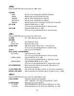
Страница 12: ...e adjusted whilst in shutter mode 4 AGC Auto gain control ON OFF 5 DC LEVEL BRIGHTNESS DC LEVEL Adjust DC level 0 255 This can only be adjusted whilst in DC lens mode VIDEO LEVEL Adjust VIDEO level 0 255 This can only be adjusted whilst in video lens mode BRIGHTNESS Adjust BRIGHTNESS level 0 255 This can only be adjusted whilst in manual lens mode 6 FLICKERLESS Removes screen flickering caused by ...

Страница 13: ...with boundary BOTTOM and RIGHT MASK 1 16 6 M COLOUR Select MASK colour WHITE GRAY BLACK SPECIAL Press the ENTER button to access the SPECIAL mode 1 SYNC Select Internal or Line Lock mode INT This mode is necessary for using the internal synchronization L L This mode is necessary for the operation of multi camera because it synchronizes the camera phase by using the external signal AC Signal 2 PHAS...

Страница 14: ... Select operating protocol COMMAND Camera controlled by RS 232C command VISTA Vista protocol PELCO D Pelco D protocol PELCO P Pelco P protocol 4 DISP MODE On screen display is ON OFF 5 DISP ITEM DISP0 Display title and camera ID DISP1 Display title camera ID and DC Level 6 TITLE 7 SAVE Save preset parameters of CAM SET MENU END Press the ENTER button to access the END mode 1 DEFAULT EXIT Set param...

Страница 15: ...ode or NIGHT mode by receiving the D N on off signal from external light sensor or IR LED LAMP This needs the D N Mode to be set to External on the OSD menu of the camera to work 3 ALARM OUT 6pin Motion detection signals are output through this port 0v going high 5v TTL on alarm 4 POWER INPUT TERMINAL This terminal accepts a DC12V or AC24V power source from a DC12V or AC24V ac 10 60 50Hz 1Hz Use C...

Страница 16: ...y turning clockwise Notes For using main functions it is recommended to use Auto Iris Lens with DC type If the lens is marked with fingerprints other marks the image quality might be poor It is recommended to use a high quality lens to improve the image quality under low illumination Video type Pin 1 Red Power source Pin 2 N C Pin 3 White Video signal Pin 4 Black GND DC type Pin 1 Damping Pin 2 Da...

Страница 17: ...Auto Exposure Auto Manual Shutter Flicker less AGC Control AUTO Shutter Speed 1 50 1 100 000 BLC Top Bottom Center Right Left Off Title A Z 0 9 Display On Off DISP0 DISP1 CAM ID 001 255 BPS 2400 4800 9600 19200 Brightness 0 255 steps Sharpness 0 15 steps Low Shutter x2 x256 13 steps Effect V Flip Rotation Mirror D N D Zoom Nega Posi B W Freeze Privacy Zone MD WDR S LEVEL 0 200 steps L LEVEL 0 200 ...

Страница 18: ...18 MEMO ...

Страница 19: ...19 Norbain SD Ltd 210 Wharfedale Road Winnersh Triangle Wokingham Berkshire RG41 5TP United Kingdom 50302395C ...

Отзывы: