background image

VE810 Series 4 User Manual

18

© 2015 Vision Engraving Systems

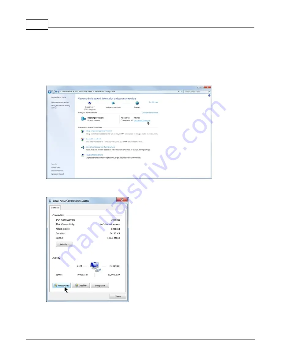
The computer's IP address will need to be set. NOTE - this should not cause any conflicts with your
computer's wireless IP address, which is determined by the computer's wireless network card. To set
the computer's IP address, open the Windows Control Panel. Depending on how you have this folder
set, you will either see Network and Internet, or you will see the Network and Sharing Center
immediately. If you see Network and Internet, select View Network Status and Tasks (which opens the
Network and Sharing Center). If you see the Network and Sharing Center, open it. Then select Local
Area Connection (as shown below).

Select Properties.

Содержание VE810 4 Series

Страница 1: ...2015 Vision Engraving Systems VE810 Series 4 User Manual Revised 8 19 2015...

Страница 2: ...author make no claim to these trademarks While every precaution has been taken in the preparation of this document the publisher and the author assume no responsibility for errors or omissions or for...

Страница 3: ...e Front Panel 52 5 Holding Down Material Part IV Step by Step Operation 55 55 1 Diamond Drag Engraving 56 Example Job 1 Diamond Drag 65 2 Rotary Engraving 66 Example Job 2 Rotary Engraving 70 3 Burnis...

Страница 4: ...n 127 4 Changing the Motor Belt 130 5 Changing the Motor Brushes 133 6 Cleaning the Fan Filter Part VII Troubleshooting 134 134 1 Engraving Problems 137 2 Mechanical Problems Part VIII Optional Access...

Страница 5: ...ertainly beneficial For information on the Vision Engraving Software see the Vision Engraving Software manual For more information on your individual computer system see your computer s user manual or...

Страница 6: ...and workmanship under normal use and service Upon written notification we will transfer the remaining warranty to a new customer This warranty shall cover all elements except for items covered by sepa...

Страница 7: ...the equipment will be in Lapse of Warranty An Extended Warranty can never again be purchased for any equipment that is in Lapse of Warranty It is the responsibility of the purchaser of the equipment t...

Страница 8: ...operate the equipment with damaged or frayed power cords loose connections or exposed extension cords where the cord could create a tripping hazard Be sure to hold the plug not the cord when disconne...

Страница 9: ...nty Card 1 Vision VE810 Installation Guide 1 White Blue or Orange USB security dongle Contains User Manual and Vision Software 1 Ethernet Network Cable 1 Crossover Cable 1 Power Cord 1 0 015 FLX Plast...

Страница 10: ...rides on 3 Y Axis Linear Rails The 1 2 inch 12 7 mm round rails that the t slot table rides on 4 Y Axis Leadscrew The screw that drives the front to back motion of the machine 5 T Slot Table Also ref...

Страница 11: ...o the material when engraving When viewed from the top turning the knob clockwise will increase pressure and turning it counter clockwise will decrease pressure 13 Spindle Pulley This is the top part...

Страница 12: ...tandard network cable DO NOT use the crossover cable when connecting to a network In this configuration the Vision VE810 will be recognized as a network device Connection to the machine in this manner...

Страница 13: ...Bit 64 Bit Windows 7 32 Bit 64 Bit Windows XP SP3 32 Bit 64 Bit not supported Ports USB port for security dongle Local or network Ethernet port to connect machine Suggested System Requirements CPU Co...

Страница 14: ...your network your hub or using the crossover cable plug into the network port on the back of your computer NOTE The crossover cable is colored gray 3 2 1 Direct Connection to Computer Direct Connecti...

Страница 15: ...Vision Engraving Systems or Windows 10 the screens are slightly different The computer will recognize the USB drive and the following screen will appear Select Continue without scanning Select Open f...

Страница 16: ...stems Locate the file named Start and double click on the file to begin the installation The screen below shows Start exe but your computer might not show the exe portion Select Step 1 Setup Machine T...

Страница 17: ...Installation 17 2015 Vision Engraving Systems When the software is installed select Finish The Connectivity Manager will search for available Vision devices...

Страница 18: ...k card To set the computer s IP address open the Windows Control Panel Depending on how you have this folder set you will either see Network and Internet or you will see the Network and Sharing Center...

Страница 19: ...tocol Version 4 TCP IPv4 Select Properties then select Use the following IP address and enter 192 168 5 100 as shown Then click in the Subnet Mask area which will populate the correct location of 255...

Страница 20: ...the machine will need to be configured in order to set up the connections properly Select the box next to the machine now listed in the Discover Machine Tools window to expand the information Then sel...

Страница 21: ...to 192 168 5 101 then select OK This sets the machine s IP address The configuration is complete at this point Close the Discover Machine Tools window and return to the Main Installation Screen to pr...

Страница 22: ...LCD screen on the front of the machine After the machine has initialized Goto Home will be displayed after initializing plug the supplied Vision USB drive into an available USB port on your computer N...

Страница 23: ...ocate the file named Start and double click on the file to start the installation The screen below shows Start exe but your computer might not show the exe portion Select Step 1 Setup Machine This ins...

Страница 24: ...stalled select Finish The Connectivity Manager will search for available Vision devices The configuration is complete at this point Close the Discover Machine Tools window and return to the Main Insta...

Страница 25: ...is located below the LCD screen on the front of the machine After the machine has initialized Goto Home will be displayed after initializing plug the supplied Vision USB drive into an available USB po...

Страница 26: ...stems Locate the file named Start and double click on the file to start the installation The screen below shows Start exe but your computer might not show the exe portion Select Step 1 Setup Machine T...

Страница 27: ...Installation 27 2015 Vision Engraving Systems When the software is installed select Finish The Connectivity Manager will search for available Vision devices...

Страница 28: ...Depending on how you have this folder set you will either see Network and Internet or you will see the Network and Sharing Center immediately If you see Network and Internet select View Network Status...

Страница 29: ...Then select Internet Protocol Version 4 TCP IPv4 Then select Properties Select Use the following IP address and enter 192 168 5 100 and set the Subnet mask to 255 255 255 0 as shown Then select OK and...

Страница 30: ...dress of the machine will need to be set to set up the connections properly Select the box next to the machine now listed in the Discover Machine Tools window to expand the information Then select Con...

Страница 31: ...ets the machine s IP address The configuration is complete at this point The new IP address should appear in a few seconds in the Discover Machine Tools window Close the Discover Machine Tools window...

Страница 32: ...User Manual 32 2015 Vision Engraving Systems 3 3 Vision Software Installation From the Main Installation Screen Select Step 2 Install Vision Software The Windows Installer will prepare the installati...

Страница 33: ...Installation 33 2015 Vision Engraving Systems Select Install The installation will proceed Select the appropriate language and select OK...

Страница 34: ...VE810 Series 4 User Manual 34 2015 Vision Engraving Systems Installation will proceed Select Next to begin the installer Select Accept the license agreement then select Next...

Страница 35: ...Installation 35 2015 Vision Engraving Systems Select Next or change the destination folder not recommended Select Next to create the folder...

Страница 36: ...ision Engraving Systems The installation will continue Select the Vision VE810 S4 then select Next If you purchase another engraving system from Vision it can be added to the machine list at a later d...

Страница 37: ...ems Select Continue to install True Type fonts and Vision Engraving Fonts on your computer The software will look for True Type fonts on your computer and allow the Vision software to use them Once th...

Страница 38: ...s step the software will install any Engraving fonts on your computer When complete click on OK In order to install the fonts from the USB drive select A Removable drive and from the drop down list se...

Страница 39: ...39 2015 Vision Engraving Systems Select OK to install to the default folder Select OK All fonts and clipart have been installed from the USB drive at this time Select OK to return to the main install...

Страница 40: ...VE810 Series 4 User Manual 40 2015 Vision Engraving Systems To complete the installation select Finish To close the Software Setup window select Finish...

Страница 41: ...ng on the Vision manuals link will give the user access to User Manuals Installation Guides Accessories and Training Videos If you were supplied with an Orange Dongle orange USB stick keep it installe...

Страница 42: ...vy load on the engraving spindle If this happens you can possibly dull the engraving cutter or the engraving quality will not be very good Fortunately engraving speeds presets for most materials are s...

Страница 43: ...e in order to reset the machine If there is a job in the machine this function will perform a dry run of the job with the red pointer on the machine The red pointer will outline the job to be engraved...

Страница 44: ...CD screen X Y Jog buttons The X Y jog buttons are used to move the position of the spindle on the T Slot table work area This is used to position graphics or to move the material The X jog buttons wil...

Страница 45: ...nd a job to the machine to be engraved Press Pause Press Start The spindle will move to the first point to be engraved and pause You can then jog the Z down until it touches the surface and press Star...

Страница 46: ...is procedure Goto Offset button When you press the Goto Offset button the engraver will return to the offset position previously set either temporary or stored Pressing this while a job is running wil...

Страница 47: ...c mode or off You can toggle between these two modes by pressing the Spindle On Off button When the light is red the spindle will be off When the light is orange the spindle will automatically turn on...

Страница 48: ...engraving job If you press the PAUSE or STOP button the vacuum will turn off for safety reasons Always make sure you have the vacuum turned on when appropriate to remove chips that will be created du...

Страница 49: ...be set from the Vision Pro software When the Engrave icon is selected select the icon with three dots to the right of All Tools as shown below Change the Z lift height value to the desired distance a...

Страница 50: ...its on the LCD from Standard to Metric ALT Stop button Holding down the ALT button and pressing the Stop button will display machine specific information The first information that will be displayed i...

Страница 51: ...machine Pressing Start will load the job and pressing Start again will run the job ALT Limits On Off button Holding down the ALT button and pressing the Limits On Off button will display a test menu...

Страница 52: ...s that remain uncut For a detailed explanation on the use of the micrometer for setting cutting depth see Example Job 4 in the Profile Cutting section Stacked Material Method Many times double sided t...

Страница 53: ...chine may not engrave characters completely Edge Guides Side View To adjust the edge guides loosen the edge guide thumbscrews and raise them above the surface of the T slot table Place the material on...

Страница 54: ...rew Once this is done the material can easily be secured by turning the quick lock vise handle When changing the engraving material simply loosen the quick lock vise handle remove the engraved materia...

Страница 55: ...ead through and practice the techniques in these example files in the sequence they are provided in this manual 4 1 Diamond Drag Engraving Engraving Non Rotating In this section we will set up to engr...

Страница 56: ...ight of the machine also known as Set Surface In this type of engraving the Proximity Sensor will automatically sense when the cutter tip contacts the material and will adjust the Z Axis height and cu...

Страница 57: ...y Step Operation 57 2015 Vision Engraving Systems The Plate Size window will appear Click on the Current Selection drop down list and select Custom Enter the plate size to be engraved for this example...

Страница 58: ...VE810 Series 4 User Manual 58 2015 Vision Engraving Systems To add text click on the Text Tools icon The flyout icons will appear then select the Text Compose icon...

Страница 59: ...ing text Note that on the top toolbar the various font editing fields have appeared The user should become familiar with the various ways fonts can be formatted with the toolbar options For this examp...

Страница 60: ...gn Blank Center as shown below from the top toolbar Note that there are several ways to align objects within the Vision software The Break Text warning may appear If so select No If Yes is chosen and...

Страница 61: ...sition upper left corner of the engraving table Note that the Multi Mat material has been placed on the t slot table in order to hold the engraving material in place Select the Engrave icon from the l...

Страница 62: ...244 mm X to the right and 8 45 inches 214 6 mm Y toward the bottom of the machine s home position the file will not run because the motion system would have to move beyond its limits When ready to sen...

Страница 63: ...d properly and you are ready to engrave select the Engrave icon from the left toolbar turn off the Dry Run option and check to make sure the Proximity Sensor see the Prox icon below is enabled then se...

Страница 64: ...64 2015 Vision Engraving Systems Make sure the material is positioned properly and secured on the engraving table then press the Start Button on the engraver to begin engraving The finished piece sho...

Страница 65: ...hand tight Then you must zero the cutter To do this you must first turn the micrometer so that the pointer points to 0 Note it is helpful to first turn the micrometer to the left clockwise until threa...

Страница 66: ...areful not to set the depth of cut greater than the material thickness This will cut completely through the material and potentially cut into the t slot table Press Start to resume engraving and to de...

Страница 67: ...atically be centered and have automatic Kerning In the below example the font was changed to Casual1 with a height of 1 250 inches and a slant of 19 degrees The top and center lines are left justified...

Страница 68: ...e Cut Toolbox shows that the Vacuum Prox Dry Run and Spindle are all enabled Since this is the second example job sending a Dry Run job to the engraver is suggested Select the Engrave Icon to send the...

Страница 69: ...from scratching the surface of the material during operation and or getting trapped between the nose cone and the material when using the proximity sensor function and causing the engraver to not engr...

Страница 70: ...utter applied to the material Burnishing requires less pressure than other types of engraving and the EZ Rider attachment applies the proper amount of pressure for burnishing Installing the EZ Rider i...

Страница 71: ...e used to view the Z position and assist in the pre loading procedure To toggle the jog speed press the B3 Button Once the correct Z position has been set press the Start button to set the surface pos...

Страница 72: ...inch 199 4 x 137 2 mm piece of coated brass also known as black brass or trophy brass The plate will use a text import function from an external text file that will be copied into a plate template an...

Страница 73: ...ht to 2 500 and 1 25 inches set the left margin to 0 175 inches and the top margin to 0 200 inches as shown then click on Apply Note that the page margins on the toolbar are located such that the top...

Страница 74: ...the middle of the Plate Object Enter any text in the format you wish to use In this example two lines of text are entered as variables it does not matter what you type The text entered is only for for...

Страница 75: ...ext and double click on the font name If the size or other parameters need to be revised use the toolbar fields to modify the font style Please note that in this example the Width Compression for the...

Страница 76: ...thod Width compress expand and Apply to Each Line Individually Deselect Word Wrap then select OK For a detailed description of all the font modifications possible refer to the Vision software help or...

Страница 77: ...text and select copy from the edit menu or right click and select copy Note that in this example the two variables are entered as subsequent lines in the text file and that there may be difficulties w...

Страница 78: ...ual 78 2015 Vision Engraving Systems Click in the center of the plate After clicking in the center of the plate all fields are merged and multiple plate objects will be created based on the number of...

Страница 79: ...l Setup icon select Metals Burnishing from the drop down list then click on OK If you choose to run a Dry Run as shown to make sure the setup is correct proceed as in prior sections to send the file t...

Страница 80: ...VE810 Series 4 User Manual 80 2015 Vision Engraving Systems In this example the plate object lines were engraved...

Страница 81: ...e cutting depth of the cutter beveler tool Setting Cut Depth for Cutter Beveler Tool Standard Method If you have measured the thickness of the material to be cut you can adjust the micrometer in two w...

Страница 82: ...urning counter clockwise 1 3 clicks Holding Down Material Secure the material on the t slot table It is best to use Multi Mat to hold the material in place but keep in mind that since we are cutting c...

Страница 83: ...ple Job 2 the Vacuum Chip Removal System is highly recommended for this application and is shown in this example First the plate size will be adjusted to the standard Vision VE810 10 x 8 inch area A s...

Страница 84: ...ng on a corner node holding down the left mouse button and dragging the corner to make the image smaller For this example the image was re sized to 0 5 x 0 5 inches 12 7 x 12 7 mm and located at X 0 7...

Страница 85: ...xt it does not matter what text is entered here It is just entered to create the text object To re size the text frame click and hold with the left mouse button on the black edge of the text frame and...

Страница 86: ...shown and from the toolbar select Arrange Text To Graphics HINT to select more than one object click on the first object hold down the Shift Key then click on additional objects The two text fields ar...

Страница 87: ...ge can be performed after engraving To change the Plate Object frames to another color red in this example select the Plate Object frame then click on the Red color icon on the bottom toolbar of the V...

Страница 88: ...there is more than one page of names each page of the file will need to have the plate frame color changed After changing the plate frame color If you try to send this file to the engraver at this po...

Страница 89: ...Defaults then make sure Engrave by Color checkbox is selected then Apply and Close In order to send the engrave file to the engraver select the Engrave icon from the left toolbar at which time the Fil...

Страница 90: ...c Engraving as the material then click on OK Make sure all options are turned on in the Cut Toolbox including Dry Run for this example file Select the Engrave icon from the Cut Toolbox to send the fil...

Страница 91: ...as in Rotary Engraving section before running the file If the Dry Run shows proper set up resend the file with the Dry Run turned off Use the proper cutting tool for the engraving application Note tha...

Страница 92: ...y for you to send another file to the engraver Since we need to change the material setting select Stop Cutting To change to the material setting for cutting select Engrave from the top toolbar menu t...

Страница 93: ...elect Engrave from the Cut Toolbox The screen will show only objects in the color selected in the Filter by Color window The page selection screen will re appear for this example choose Current Page a...

Страница 94: ...VE810 Series 4 User Manual 94 2015 Vision Engraving Systems Note The Filter by Color screen will once again appear Since we have no further colors to send to the engraver select Stop Cutting...

Страница 95: ...oftware The Vision 9 software has a new and vastly simplified method of creating a vector outline from a bitmap image Vector outlines are automatically created when the bitmap is imported in the drawi...

Страница 96: ...then choose the file and select Import The next screen has only one adjustment Alignment Bitmap Density There is a slider bar for darkening or lightening the image to show more or less detail The def...

Страница 97: ...e interior engraved the Hatch Fill tool is used As an example if a simple circle is drawn in the Vision 9 software but the user wants to engrave the entire circle not just the outline a hatch fill is...

Страница 98: ...r tip width of 0 020 is being used then the recommended overlap for the Hatch Fill would be 0 020 x 25 0 005 inches To produce an overlap of 0 005 inches subtract 0 005 from the cutter tip width 0 020...

Страница 99: ...o the engraver You may want to change the hatch fill color to match the color of the outline although it is not necessary Filling Outline Text Hatch fills can be applied to outline text but not single...

Страница 100: ...al 100 2015 Vision Engraving Systems Before filling text the user must first select the text with the Select Tools icon Click on the Select Tools icon and select the text to apply the hatch fill to Se...

Страница 101: ...nd color as desired then select Close The file is ready to be sent to the engraver Complex Hatch Fills Some graphics have portions that do not need to be engraved and are within the boundaries of outs...

Страница 102: ...y detect portions of the graphic that are within outside vector lines and will create a hatch fill with the center portions left as unfilled Press the F3 button on the computer keyboard to select all...

Страница 103: ...015 Vision Engraving Systems If this looks correct select the Hatch Fill icon The hatch fill will be applied Adjust the tool options as desired and select Close from the toolbar menu The file is ready...

Страница 104: ...0 has features to help with positioning items and graphics Two of these features are Setting a Custom Home Position and using the Vise or Center driver Both of these techniques will assist the user wh...

Страница 105: ...r Move the spindle over the material and position the laser pointer so that it is in the upper left hand corner of the engraving area you wish to define Then click on Next in the Measure Wizard window...

Страница 106: ...llow the instructions on your machine or controller to have the machine outline this engraving area with the red dot laser pointer If the area appears to be correct click on OK in the Plate Size windo...

Страница 107: ...o a point on your material in the upper left hand corner of the area to be engraved An example of this is shown below using an electrical outlet cover In this example the user has identified the engra...

Страница 108: ...Engraving Systems In the Vision 9 software begin by making the plate size the same as the engraving area 1 25 inches x 0 25 inches as shown below Add text The Frame Text Compose tool will center and a...

Страница 109: ...directly over the upper left hand corner of the engraving area The pictures below show the spindle cutter tip correctly positioned in the upper left corner of the engraving area To set this point as...

Страница 110: ...aver including a simple rectangle that is slightly smaller than the engraving area as shown below The Red Dot Laser Pointer will follow the path of this rectangle and outline the engraving area This c...

Страница 111: ...d on this center location An illustration of this process is shown below For simplicity in this example a circular piece of acrylic will be engraved The material is 3 inches in diameter and an engravi...

Страница 112: ...Vision Engraving Systems The Plot widow will appear and from the Selected Driver drop down list select the VE810 S4 Vise driver If this driver has not been installed refer to the section Installing A...

Страница 113: ...ion 113 2015 Vision Engraving Systems Under the Installed Drivers section make sure the VE810 S4 Vise driver is selected then select Create custom copy of selected driver Type in VE810 Center Driver t...

Страница 114: ...VE810 Series 4 User Manual 114 2015 Vision Engraving Systems Click on Apply then click on OK Select the VE810 Center Driver we just created from the Selected Driver drop down list...

Страница 115: ...he Move fields to 0 for both X and Y move click on Apply and then click on Close Set the plate size to match the engraving area you determined for your item In this example a 1 75 x 0 75 size was ente...

Страница 116: ...set the home position set offset for the item we are engraving Move the spindle to the center of the engraving area In this case it is the center of the 3 0 piece of acrylic Press the Set Offset butt...

Страница 117: ...r Select Engrave from the Cut Toolbox then press the Start button on the engraver to begin engraving the job You may want to perform a dry run before engraving to check for setup errors Since we have...

Страница 118: ...ick on Cutting Devices The Installation Wizard will begin The Driver Installation Wizard window will appear Select the machine series from the Manufacturer list on the left side by placing a check mar...

Страница 119: ...ically the driver s will then be available in the Device drop down list If you wish to uninstall driver s simply follow the above procedure and deselect the drivers by removing the check mark to the l...

Страница 120: ...aning procedure of Multi Mat Cleaning Multi Mat is simple and easy Merely use a soft sponge and running water to remove chips dust or dirt and then allow to dry No chemicals or cleaners are required H...

Страница 121: ...d the vacuum tube leading to the nose cone Reinstall the nose cone and the vacuum hose Without a vacuum chip removal system you should remove the cutter before attempting to clean the nose cone The no...

Страница 122: ...OFF you can move the carriage table and spindle manually to access areas for cleaning and lubricating the machine To move the table press on the front or rear edge of the table To move the carriage p...

Страница 123: ...removed It holds a cable clamp inside the back cover of the machine To remove the center screw reach inside the machine with a 11 32 nut driver to hold the nut and remove the screw with a Phillips sc...

Страница 124: ...r Remove the four screws on each side of the Carriage Cover Cleaning Apply isopropyl alcohol to a paper towel and wipe down the X Axis carriage leadscrew and the stainless steel rails for the carriage...

Страница 125: ...able with the table in the fully extended forward and fully retracted positions Raise and lower the spindle to access the upper and lower sections of the spindle rail The rail is located behind the sp...

Страница 126: ...ricants After completing this procedure and re installing the carriage and top covers the lubricants should be worked in to the motion system for several minutes prior to using the machine To move the...

Страница 127: ...wing explains the procedure for changing the motor belt Cover Removal Top Cover Screws Remove the two top cover screws shown below Back Cover Screws Remove the five back cover screws shown below The c...

Страница 128: ...128 2015 Vision Engraving Systems Spindle Cover To remove the spindle cover slide the cover up Squeezing the sides of the cover will facilitate removal Carriage Cover Remove the four screws on each s...

Страница 129: ...roll the front edge of the belt up towards the top of the spindle and over the lip at the top To replace the belt align the belt in the motor pulley and pull the belt forward and roll it down over the...

Страница 130: ...ss than 1 8 inch 3 mm Cover Removal Top Cover Screws Remove the two top cover screws shown below Back Cover Screws Remove the five back cover screws shown below The center screw does not absolutely ne...

Страница 131: ...15 Vision Engraving Systems Spindle Cover To remove the spindle cover slide the cover up Squeezing the sides of the cover will facilitate removal Carriage Cover Remove the four screws on each side of...

Страница 132: ...acement Use a flat blade screwdriver to loosen the motor brush cap Inspect the motor brush for length If the length is under 1 8 inch 3 mm the motor brush needs to be replaced If the motor brush is ov...

Страница 133: ...filter be removed weekly and cleaned to ensure proper cooling of the electronics 1 Unplug the power cable that goes into the back of the machine 2 Remove the filter guard by using a small flat blade s...

Страница 134: ...t zeroed to your material 2 When burnishing there may not be enough pre load set to adjust for material thickness changes If using the Set Surface function to control engraving depth and not the Prox...

Страница 135: ...rpendicular to the material surface 5 Turn the spindle RPM speed up Problem Poor letter quality Possible solutions 1 The engraving speed may be too fast Engraving quality improves with the right engra...

Страница 136: ...ision Engraving Systems the surface and are more easily worn thus sometimes skipping across the surface 3 Increase the pre load of the burnishing adapter 4 Try other materials Same reasons as above So...

Страница 137: ...ing the Spindle control to OFF If the noise persists it may be confined to the X Y or Z axis Check for proper lubrication of lead screws Follow lubrication instructions in the Maintenance section If t...

Страница 138: ...can clog the nose cone and or get trapped between the nose cone and the material which will cause engraving cutting depth inconsistencies potentially scratch the surface of the material and cause over...

Страница 139: ...he T slot table surface and position it over the edge of the engraving stock The downward clamping force eliminates bowing This clamp can be used with material up to 1 4 thick Push Down Clamps This do...

Страница 140: ...most applications This clamp will hold material thicknesses of 020 032 062 and 125 by rotating the clamp and tightening a thumbscrew Corner Clamps This clamp is designed to hold down square or rectan...

Страница 141: ...and Pantographs These fixtures enable engraving on uniquely shaped items such as pens lighters knives keychains and more Universal Clamping Bars w Medallion Holder These clamping bars hold 1 to 3 roun...

Страница 142: ...ns coasters paperweights dog tags and other round objects Usable with the Quick Lock or Versa Vise Adjustable Pen Fixture Enables engraving on most pens and cylindrical items that vary in diameter fro...

Страница 143: ...his is a double sided fixture that when turned in one direction accommodates a pen and when turned in the other direction accommodates a medallion seal or other circular item With a space for the eye...

Страница 144: ...ecifically designed for T slot table users The cam type locking device allows for quick changing of parts This vise is supplied with a removable front clamping plate which allows for the holding of th...

Страница 145: ......

Отзывы:

Похожие инструкции для VE810 4 Series