Vision Series 5 Controller User Manual
120
© 2019 Vision Engraving Systems
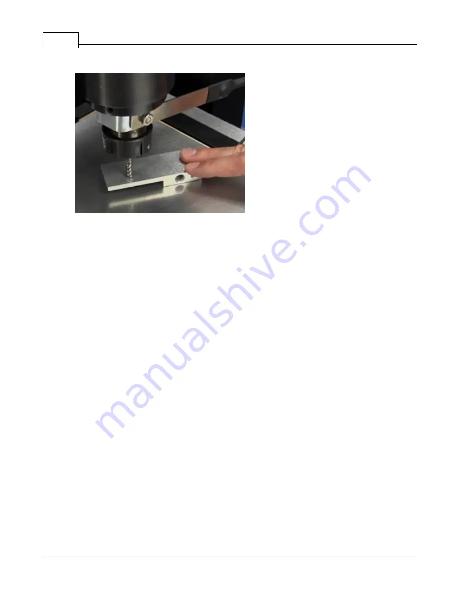
CAUTION: Keep hands and fingers away from the spindle and cutter when performing this
procedure! Serious injury may result. Do not place your hands or fingers below the cutter when
setting the surface of your material!
To set the surface of your material:
1. Connect the sensor cable.
2. Install the Spindle Clamp on the bottom of the spindle.
3. Use the X and Y buttons on the Pendant to move the spindle over your material.
4. Place the Sensor Block on top of your material and hold as shown above.
5. Press the Set Surface button on the Pendant.
6. Press and Hold the Set Surface Button until the cutter tip touches the top of the Sensor Block.
The spindle will move down and stop when the cutter tip just touches the top of the Sensor
Block. The Controller will automatically calibrate and set the surface position of your material,
then move the spindle up approximately 1/4 inch and stop.
7. Release the Set Surface button.
8. Press the Go to Home button on the Pendant.
NOTE: The design of the Sensor Block is such that if the sensor does not detect the cutter tip
contacting the Sensor Block, the block will begin to tilt downward. If this occurs, release the Set
Surface button immediately and check for proper installation of the Sensor Cable and Spindle
Clamp.
Diamond drag engraving with a proximity sensor
Make sure that the proximity sensor is turned on. When you run the job, the spindle will go down until it
touches the material and finds the surface automatically. If you want to change the lift amount of the
cutter between characters, you will need to do the following steps:
1. Press the menu button on the controller. Note: If you are in the middle of engraving a job, press
the pause button before pressing the menu button.
2. Use the Y jog up and down buttons to select Z Lift Height and press Enter.
3. Enter the lift height using the numeric buttons on the Vision controller and press Enter.
4. Press Exit to return to the main screen.
5. The Z lift height is now set. Press Start to run the job or resume engraving.
Содержание 1624R
Страница 1: ...2019 Vision Engraving Systems Vision 1624R 2525 and 2550 Series 5 User Guide Revised 7 3 2019...
Страница 15: ...1624R 2525 and 2550 Series 5 Installation 15 2019 Vision Engraving Systems Vision 2550 installation layout...
Страница 20: ...Vision Series 5 Controller User Manual 20 2019 Vision Engraving Systems 1624R Diagrams...
Страница 21: ...1624R 2525 and 2550 Series 5 Installation 21 2019 Vision Engraving Systems...
Страница 22: ...Vision Series 5 Controller User Manual 22 2019 Vision Engraving Systems...
Страница 26: ...Vision Series 5 Controller User Manual 26 2019 Vision Engraving Systems 2525 2550 Diagrams...
Страница 27: ...1624R 2525 and 2550 Series 5 Installation 27 2019 Vision Engraving Systems...
Страница 29: ...1624R 2525 and 2550 Series 5 Installation 29 2019 Vision Engraving Systems Vacuum Table Top View...
Страница 34: ...Vision Series 5 Controller User Manual 34 2019 Vision Engraving Systems Vision Series 5 controller rear view...
Страница 37: ...1624R 2525 and 2550 Series 5 Installation 37 2019 Vision Engraving Systems...
Страница 39: ...1624R 2525 and 2550 Series 5 Installation 39 2019 Vision Engraving Systems Engraving Head Diagram Installed...
Страница 52: ...Vision Series 5 Controller User Manual 52 2019 Vision Engraving Systems Router Rail Plate Carriage rear view...
Страница 54: ...Vision Series 5 Controller User Manual 54 2019 Vision Engraving Systems...
Страница 58: ...Vision Series 5 Controller User Manual 58 2019 Vision Engraving Systems...
Страница 67: ...Vision Mov UI Software Installation 67 2019 Vision Engraving Systems Select Step 1 Setup Machine...
Страница 81: ...Vision Software Installation 81 2019 Vision Engraving Systems Select Continue on the Font Installation screen...
Страница 128: ...Vision Series 5 Controller User Manual 128 2019 Vision Engraving Systems...
Страница 130: ...Vision Series 5 Controller User Manual 130 2019 Vision Engraving Systems...
Страница 131: ......


