


Manual VIPA System SLIO
Chapter 2 Hardware description
HB300E - IM - RE_053-1DN00 - Rev. 11/21
2-3
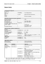
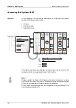
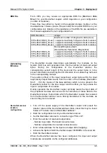
Structure
12
1
5
7
8
10
4
2
3
6
9
13
11
[1]
[2]
[3]
[4]
[5]
[6]
[7]
[8]
[9]
[10]
[11]
[12]
[13]
Locking lever terminal module
Labeling strip bus interface
LED status indication bus interface
Labeling strip power module
LED status indication power module
Backplane bus
DC 24V power section supply
Power module
DeviceNet connector bus interface
Unlocking lever power module
Bus interface
Terminal
Address selector
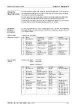
LED
Color
Description
PWR green
●
Bus interface is power supplied
SF red
●
Error on DeviceNet or System SLIO bus
RD green
●
Status System SLIO bus
MT yellow
●
Status DeviceNet
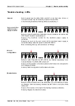
Status indication
bus interface
PWR
SF
RD
MT
For the fast diagnosis of the current module status 4 LEDs are on the front
side.
You may find a detailed description of the LEDs in the chapter
"Deployment" at "Status indication - Diagnostics".
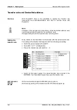
LED
Color
Description
PWR IO
green
●
Power section supply OK
PF IO
red
●
Fuse power section supply defective
(Power fail)
PWR green
●
Electronic section supply OK
PF red
●
Fuse electronic section supply defective
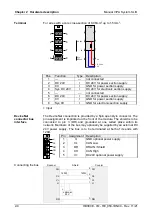
Status indication
power module
PWR IO
PF IO
PWR
PF
on:
●
053-1DN00
Содержание SLIO IM 053-1DN00
Страница 1: ...VIPA System SLIO IM 053 1DN00 Manual HB300E_IM RE_053 1DN00 Rev 11 21 May 2011...
Страница 4: ...Contents Manual VIPA System SLIO ii HB300E IM RE_053 1DN00 Rev 11 21...
Страница 8: ...Safety information Manual VIPA System SLIO 4 HB300E IM RE_053 1DN00 Rev 11 21...
Страница 28: ...Chapter 1 Basics and Assembly Manual VIPA System SLIO 1 20 HB300E IM RE_053 1DN00 Rev 11 21...


