VIP Vision Residential IP Intercom Installation Guide - v1.3 Issued April 2017
26
Router
Device
IP Adresses
Subnet Mask
Gateway
Room Number VTO Number
Door Station 1
10.1.1.110
255.255.255.0
10.1.1.1
6901
Door Station 2
10.1.1.111
255.255.255.0
10.1.1.1
6902
Master Indoor
Monitor
10.1.1.112
255.255.255.0
10.1.1.1
9901
Extension
Indoor Monitor
10.1.1.113
255.255.255.0
10.1.1.1
9901-1
2.6
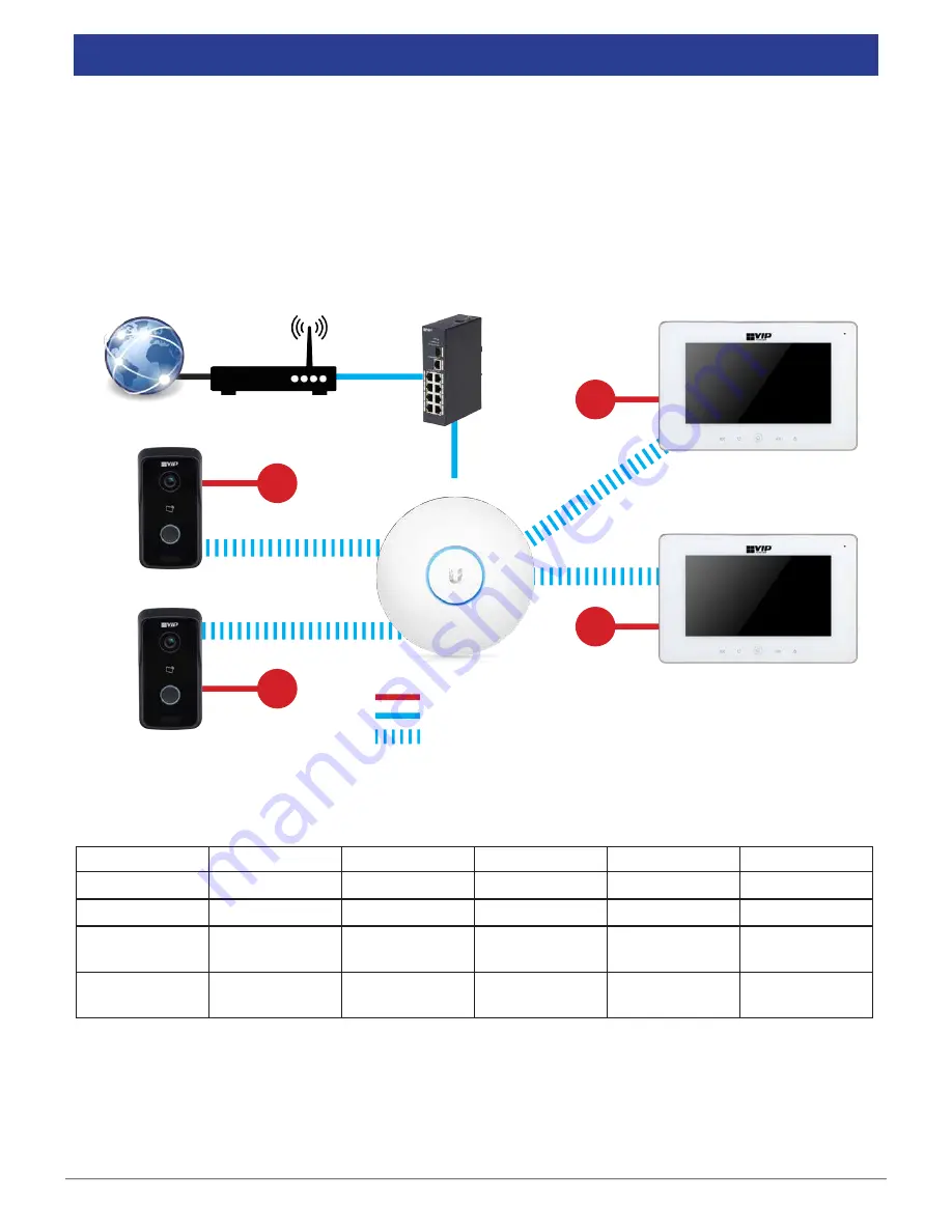
2 Indoor Monitors to 2 Door Stations via a Wireless Access Point (Wireless)
This configuration allows you to connect your Indoor Monitors and Door Stations together through a wireless
access point, and provide them with network access.
The following is required for this installation:
•
12VDC power for both the Door Station and Indoor Monitors
•
A Cat5 cable between the Door Stations and an existing computer network to configure the Door Stations
•
A Windows computer for configuration
In this example, we are going to connect the Door Stations and Indoor Monitors to a Wireless Access Point
and assign static IP addresses to the Door Stations and Indoor Monitors.
+ / -
12VDC
+ / -
12VDC
+ / -
12VDC
+ / -
12VDC
Power
Wireless signal
Indoor Monitor
Indoor Monitor
Door Station
Door Station
Internet
Cat5e
Wireless Access Point
Switch


