background image

31

www.vintageair.com

900194 REV B 09/16/19, PG 31 OF 42

246204-PUA

3 POT ECU ASM

246204-PUA

3 POT ECU ASM

246204-PUA

3 POT ECU ASM

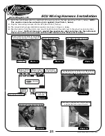
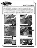
ECU Wiring Harness Installation

Route the violet power wire to a switched 12V power source on the fuse panel (See Photo 1, below). NOTE: 

This requires a male fuse extension (not supplied) (See Photo 2, below).

Plug the main wiring harness into the ECU (See Photo 3, below).
The correct ECU harness installation locations are shown in Figure 1, below.
Peal the backing from the Velcro, and mount the ECU behind the dash next to the glove box opening (See 

Photo 4, below). NOTE: At this point, reinstall the speedometer cable and plugs into the instrument 

cluster and install it into the dash with the OEM hardware (See Photos 5 & 6, below).

1.

2.
3.
4.

Photo 1

Route Violet Power Wire to Switched 

12V Power Source on Fuse Panel

Photo 2

Plug Main Harness into ECU

Photo 4

Peal Backing From Velcro And Mount ECU 

Behind Dash Next To Glove Box Opening

Male Fuse Extension

Photo 3

Figure 1

Photo 5

Photo 6

Reconnect Speedometer Cable 

Reconnect Instrument Cluster Wiring 

and Install Instrument Cluster

Stepper Motor 

Harnesses

Thermistor 

Probe Harness

Blower Speed 

Control Harness

Main Wiring Harness

Control Panel 

Harness

Fuse Panel

Содержание 751152

Страница 1: ...gistered Company 1967 Ford F 100 Evaporator Kit 751152 18865 Goll St San Antonio TX 78266 Phone 800 862 6658 Sales sales vintageair com Tech Support tech vintageair com www vintageair com 900194 REV B 09 16 19 PG 1 OF 42 ...

Страница 2: ...ion Radio and Control Panel Installation with Heater Mounted OEM Controls Passenger Side Plenum Assembly Louver Bezel Installation Duct Hose Installation Driver Side Underdash Louver Installation Drain Hose Installation ECU Wiring Harness Installation Glove Box Installation Heater Control Valve Installation A C Hose Installation Wiring Final Steps Final Steps Wiring Diagram Gen IV Wiring Connectio...

Страница 3: ... beginning installation open all packages and check contents of shipment Please report any shortages directly to Vintage Air within 15 days After 15 days Vintage Air will not be responsible for missing or damaged items NOTE Images may not depict actual parts and quantities Refer to packing list for actual parts and quantities 1 2 Gen IV Evaporator Sub Case 744019 Accessory Kit 791152 ...

Страница 4: ...r A C system This is especially important with the receiver drier Additionally when caps are removed for assembly BE CAREFUL Some components are shipped under pressure with dry nitrogen Evacuate the System for 35 45 Minutes Ensure that system components Drier compressor evaporator and condenser are at a temperature of at least 85 F On a cool day the components can be heated with a heat gun or by r...

Страница 5: ... sensitive to voltage spikes on the power leads which can cause unexpected resets strange behavior and or permanent damage Vintage Air strives to harden our products against these types of electrical noise but there is a point where a vehicle s electrical system can be degraded so much that nothing can help Radio interference capacitors should be available at most auto and truck parts suppliers Th...

Страница 6: ...tions illustrations diagrams Retain OEM bolts washers and nuts as some hardware will be reused Perform the Following Photo 1 Place Jack Stand Under Axle Bar Photo 3 Remove 2 Heater Hoses at Firewall Photo 5 Remove Heater Hose at Water Pump Photo 2 Disconnect Cable Heater Control Valve Loosen Cable Clamp Photo 4 Remove Heater Hose at Intake Photo 6 Remove 3 Heater Core Mounting Nuts Firewall Engine...

Страница 7: ...ust be removed to allow clearance when installing the new glove box Disconnect the cables and wiring from the OEM heater assembly Remove the OEM heater assembly by separating the rubber boot from fresh air inlet assembly discard See Photo 3 below Remove the fresh air inlet assembly from the kick panel by removing the 5 OEM screws See Photo 4 below 1 2 3 4 5 6 Photo 2 Photo 4 Photo 3 Remove OEM Hea...

Страница 8: ...ad adapter counterclockwise and remove See Photo 6 below C Remove the fan switch bezel See Photo 6 below and the rest of the fan switch assembly out from behind the dash D Remove the remaining 2 pull knobs by unscrewing the 2 jam nuts from the back of the dash See Photo 7 below E Remove the bracket See Photo 7 below then remove the pull knobs from the front of the dash See Photo 8 below Disconnect...

Страница 9: ...nstrument cluster See Photo 12 below Remove the dash pad by removing the 14 dash pad nuts retain See Photo 13 below NOTE The location of the dash pad nuts is shown in Photo 13 below Remove the defrost ducts and hoses from the dash defrost outlets 10 11 12 13 14 Disconnect Speedometer Cable Remove 4 Instrument Cluster Bezel Screws Unplug Instrument Cluster Wiring Location of 14 Dash Pad Nuts Dash P...

Страница 10: ...ead screws See Photo 5 below Reinstall the dash pad at this time Defrost Duct 491655 Photo 1 Photo 3 Place Defrost Duct into Dash Opening Photo 2 Defrost Duct Outlets Mark and Drill 2 11 64 Holes Figure 1 Photo 4 Place the Defrost Duct into Dash Defrost Duct Outlet Photo 5 2 8 x 1 2 Pan Head Screws Condenser Assembly and Installation 1 2 Refer to separate instructions included with the condenser k...

Страница 11: ... The measurement starts at the kick panel and runs along the section where the firewall meets the floorboard Remove the measured section of insulation from the firewall and clean the area See Photo 4 below Remove the OEM firewall insulation retainer See Photo 5 below Enlarge the OEM firewall insulation retainer hole to 5 8 See Photo 6 below Passenger Side Inner Fender Kick Panel Grommet Mark and D...

Страница 12: ...r lead grommet See Photo 3 below Photo 1 Photo 2 Photo 3 OEM Hole Under Battery Tray Enlarge Hole to 7 8 Mark and Drill 9 32 Hole Battery Tray Enlarged 7 8 Hole Indented Section Passenger Side Wheel Well and Firewall Modification Cont 7 8 Using the heater line opening closest to the passenger side for reference mark and drill a 1 hole directly under the heater line hole on the beveled ledge See Ph...

Страница 13: ...new heat blocking insulation in the area of the firewall that was removed being careful not to cover the marked area from the evaporator bracket base and the 1 2 ID x 1 OD grommet See Photos 5 6 below NOTE During the evaporator installation if the evaporator unit does not fit properly look for places where the insulation may be interfering with the evaporator clearance Trim the insulation as neede...

Страница 14: ...low NOTE Soapy water may be used to ease insertion of the A C hoses through the grommets but be sure the hoses are capped to prevent water from getting inside Figure O ring Installs Over Male Insert to Swaged Lip O ring 6 O ring 8 O ring 10 O ring O ring Supplied Oil for O rings Male Insert Female Nut Hold With This Wrench Twist With This Wrench Lubricating O rings For a proper seal of fittings In...

Страница 15: ...plate using 2 10 x 1 2 sheet metal screws into the previously drilled 5 32 holes in the inner fender kick panel grommet location See Photo 12 below Route the 6 and 10 A C hoses through the kick panel opening in the passenger compartment A C Hose Routing Kick Panel Cap Installation Cont 5 6 7 8 9 10 11 12 Route 10 90 Hose Fitting Through Firewall Cover Plate Photo 9 Photo 8 Photo 10 Photo 11 Photo ...

Страница 16: ...p grommet See Photo 16 below Apply silicone around the kick panel mating surface for a water tight seal See Figure 1 below Install the kick panel cap onto the kick panel opening and secure using 5 14 x 3 4 sheet metal screws See Photo 17 below A C Hose Routing Kick Panel Cap Installation Cont 13 14 15 16 17 18 Photo 13 Photo 14 Photo 15 Photo 16 Photo 17 Kick Panel Cap 646957 Route 10 A C Hose 90 ...

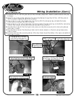
Страница 17: ...ick panel See Photo 19 below Photo 18 Drill 3 16 Hole 14 x 3 4 Sheet Metal Screw Photo 19 Wiring Installation 1 2 3 Disconnect the circuit breaker from the main wiring harness See Photo 1 below Enlarge the hole on the relay mounting tab to accommodate the 14 x 3 4 sheet metal screw installed on the kick panel cap See Photo 2 below Route the heater control valve plug through the 3 8 ID x 7 8 OD gro...

Страница 18: ...ite connector from the heater control valve into the white connector on the main wiring harness See Photo 7 below Plug the white connector from the blower motor into the white connector on the main wiring harness See Photo 8 below Route the red and white wires along the top of the inner fender toward the battery in the engine compartment See Photo 9 below Route Red and White Wires Toward Battery P...

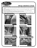
Страница 19: ...cle body and secure it using 2 10 x 1 2 sheet metal screws Reconnect the positive wires to the circuit breaker See Photo 14 below Crimp the supplied 5 16 ring terminals to the white ground wires and connect them to the negative side of the battery See Photo 15 below Photo 11 Photo 10 Photo 12 Photo 13 Photo 14 Photo 15 Crimp 5 16 Ring Terminals to White Ground Wires and Connect to Negative Side of...

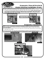
Страница 20: ... with a properly lubricated O ring onto the evaporator unit lower heater coil fitting See Figure 1 Page 21 and Photo 5 below Install the 10 heater water pump hardline with a properly lubricated o ring onto the evaporator upper heater coil fitting See Figure 1 Page 21 and Photo 6 below Heater Intake Hardline 081160 Heater Water Pump Hardline 081161 Photo 1 Install 10 Heater Intake Hardline onto Low...

Страница 21: ...ed 6 O ring See Figure 1 Page 14 and Photo 3 below Photo 1 Photo 2 Photo 3 Clean Back of This Area Clean This Area Install 6 Drier Evaporator A C Hose onto Expansion Valve 6 7 Apply double sided tape onto the evaporator firewall bracket as shown in Photo 7 below Remove the double sided tape backing and install the firewall rubber boot over the 2 heater hardlines Keep the hardlines centered and tig...

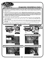
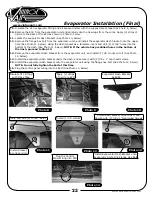
Страница 22: ...the hardlines against the firewall may loosen one or both of the fittings on the heater which could result in a leak A 2 x 4 block of wood may be put between the dash and the evaporator unit to keep it in place if necessary See Photo 5 below Reinstall the caps onto the heater hardlines From the engine compartment install 2 1 4 nylon sleeve washers and 2 1 4 20 x 3 4 serrated flange hex bolts into ...

Страница 23: ...illed holes in the bottom of the dash proceed to Step 13 Remove the evaporator dash bracket from the evaporator unit and install 2 8 U nuts onto it See Photo 12 below Install the evaporator dash bracket under the dash and secure it with 2 8 x 1 oval head screws Install the evaporator dash bracket onto the evaporator unit using the flange hex bolt See Photo 14 below NOTE Do not fully tighten the bo...

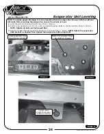
Страница 24: ... See Photo 1 below At this time tighten the 3 1 4 20 x 3 4 serrated flange hex bolts on the firewall See Photo 2 below NOTE Tighten all bolts on the firewall first Tighten the dash bracket evaporator flange hex bolt See Photo 3 below NOTE Adjust the evaporator dash bracket as needed then tighten the evaporator button head bolt Level Evaporator Unit Fore Aft and Left Right Photo 1 Tighten Dash Brac...

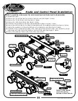
Страница 25: ...stall the rotary pot bracket assembly of the control panel from behind the dash and reinstall the control panel bezel jam nuts and control knobs on the front of the dash See Figure 4 below Remove the protective film from the front of the control knobs NOTE To install the control panel the control panel bezel and knobs must be disassembled Set Screw Rotary Pot Assembly Red White Red White Red White...

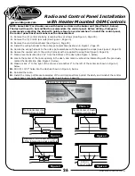
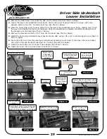
Страница 26: ...re the unused wire to the wiring harness with a supplied tie wrap See Figure 3 Page 25 Mark a level horizontal line 2 from the bottom of the dash See Figure 1 below Locate the center of the radio opening in the dash and mark a vertical line intersecting with the previously marked horizontal line See Figure 2 below Make a mark 2 to the right of the center and another 2 to the left of the center as ...

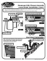
Страница 27: ... clip on the dash inlet of the plenum assembly is installed onto the evaporator unit dash outlet If not you may need to lightly push the evaporator unit toward the firewall and push up on the plenum assembly to properly install the dash inlet See Photos 5 6 below and Figure 1 Page 28 Photo 1 Photo 4 Passenger Side Plenum Assembly Louver Bezel 491659 Louvers Without Hose Adapters 490523 2 10 32 x 1...

Страница 28: ...e bolts See Photo 7 below Install the 3 louvers without hose adapters into the plenum assembly See Photo 8 below 8 Flat Washer 10 32 Nut with Star Washer 10 32 x 1 Hex Machine Screw Dash Passenger Side Plenum Assembly Louver Bezel Plenum Assembly Dash Inlet Evaporator Case Figure 1 NOTE During the installation of the defrost duct hoses ensure there is enough clearance around the passenger side win...

Страница 29: ...sing a 8 x 3 4 countersunk screw as shown in Photo 5 below Route the duct hose from the passenger side plenum assembly louver bezel to the driver side louver bezel and insert it through the bezel opening 2 to 3 inches See Photo 6 below Install the duct hose onto the louver hose adapter See Photo 7 below Insert the louver into the louver bezel See Photo 8 below Photo 3 Photo 4 Install Bezel onto Da...

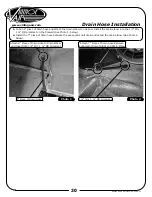
Страница 30: ...D x 1 OD grommet on the firewall See Photo 1 below Install the 7 piece of drain hose between the evaporator unit drain outlet and the drain elbow See Photo 2 below 1 2 Photo 1 Photo 2 Attach 7 Piece of Drain Hose Between Evaporator Drain Outlet and Drain Elbow 1 2 ID x 1 OD Grommet Attach 8 Piece of Drain Hose to Drain Elbow and Insert into 1 2 ID x 1 OD Grommet 8 Piece of Drain Hose ...

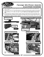
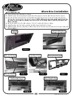
Страница 31: ...e ECU behind the dash next to the glove box opening See Photo 4 below NOTE At this point reinstall the speedometer cable and plugs into the instrument cluster and install it into the dash with the OEM hardware See Photos 5 6 below 1 2 3 4 Photo 1 Route Violet Power Wire to Switched 12V Power Source on Fuse Panel Photo 2 Plug Main Harness into ECU Photo 4 Peal Backing From Velcro And Mount ECU Behi...

Страница 32: ... slightly notch the corner of the hinge where it hits the glovebox See Photo 4 below Secure the glove box to the dash using 6 8 x 1 2 screws See Figure 1 below Install the glove box door latch using the 2 OEM screws See Photo 5 below Install the glove box door using the 3 OEM screws 2 for the lower mounts and one for the door cable See Photo 6 below 1 2 3 4 5 6 Photo 1 Glove Box 491656 Figure 1 In...

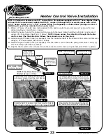
Страница 33: ...e intake manifold to the heater control valve and secure it using 2 12 hose clamps See Photo 3 below Install a length of heater hose not supplied from the heater core to the water pump and secure it using 2 12 hose clamps See Photo 4 below Plug the heater control valve connector into the connector on the main wiring harness See Photo 5 below 1 2 3 4 5 NOTE 1 Vintage Air Systems use 5 8 connections...

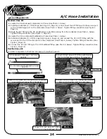
Страница 34: ...and connect the 90 fitting with the service port to the 8 discharge port on the compressor See Photo 2 below Tighten fitting connection See Figure 1 Page 14 Route the 45 fitting to the 8 condenser core hardline coming from the condenser See Photo 3 below Tighten fitting connection See Figure 1 Page 14 Locate the 10 compressor bulkhead A C hose See Photo 1 below Install and lubricate 2 10 O rings S...

Страница 35: ... lead wire to the 10 A C hose with the supplied tie wraps Under the fenderwell continue routing the compressor lead along the 10 A C hose toward the drier Crimp a 1 4 female terminal onto the compressor lead and connect it to the safety switch See Photo 6 below Secure the compressor lead to the 10 A C hose with tie wraps Photo 6 Crimp 1 4 Female Terminal onto Compressor Lead and Connect to Safety ...

Страница 36: ...eze recommendations will cause heated core to corrode prematurely and possibly burst in A C mode and or freezing weather voiding your warranty Double check all fittings brackets and belts for tightness Vintage Air recommends that all A C systems be serviced by a licensed automotive A C technician Evacuate the system for a minimum of 45 minutes prior to charging and perform a leak check prior to se...

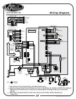
Страница 37: ...07 VUR 232002 VUA CIRCUIT BREAKER 30 AMP WIDE OPEN THROTTLE SWITCH OPTIONAL DASH LAMP IF USED Dash Lamp Is Used Only With Type 232007 VUR Harness Warning Always Mount Circuit Breaker As Close to the Battery As Possible NOTE Wire Between Battery and Circuit Breaker Is Unprotected and Should Be Carefully Routed to Avoid a Short Circuit Wide Open Throttle Switch Contacts Close Only at Full Throttle W...

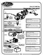
Страница 38: ...pressor Body Is Grounded Trinary Switch Connect According To Trinary Switch Wiring Diagram Install With Servo Motor Facing Down As Shown Note Flow Direction Arrow Molded Into Valve Body And Install Accordingly White Must Run To Battery Red May Run To Battery Or Starter Mount Circuit Breaker As Close to Battery As Possible Heater Control Valve Binary Trinary Compressor Circuit Breaker Battery CONTR...

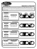
Страница 39: ...etween This lever knob controls the temperature from HOT to COLD Blower Speed Mode Control Temperature Control Temperature Control Temperature Control Temperature Control Mode Control Mode Control Mode Control For maximum heating adjust to hottest position Adjust between HOT and COLD to reach desired temperature Adjust to desired mode position FLOOR position recommended On Gen IV systems with thre...

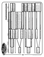
Страница 40: ...s be hot If the ground side of the blower is shorted to chassis ground the blower will run on HI Replace BSC This will require removal of evaporator from vehicle No other part replacements should be necessary Compressor will not turn on All other functions work 2 System is not charged System must be charged for compressor to engage Charge system or bypass pressure switch Danger Never bypass safety...

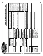
Страница 41: ...tion No mode change at all Check for damaged mode switch or potentiometer and associated wiring Partial function of mode doors Typically caused by evaporator housing installed in a bind in the vehicle Be sure all mounting locations line up and don t have to be forced into position Blower turns on and off rapidly 6 Battery voltage is at least 12V Check for at least 12V at circuit breaker Ensure all...

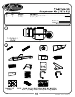
Страница 42: ...1152 No 1 2 Qty 1 1 Part No 744019 791152 Description Gen IV Evaporator Sub Case Accessory Kit NOTE Images may not depict actual parts and quantities Refer to packing list for actual parts and quantities 1 2 Gen IV Evaporator Sub Case 744019 Accessory Kit 791152 Checked By Packed By Date ...

Отзывы: