background image


- 4 -

  Use dry nitrogen to purge the system. 

  Do not overcharge the refrigeration system. 

  Do not leave replacement compressor open to the atmosphere for more 

than 10 minutes. 

  Do not operate the compressor without refrigerant charge in the system. 

  Do not use the compressor if the rubber plugs on the replacement 

compressor appear to have been tampered or removed. 

  Always replace the filter-drier when performing any repairs on the sealed 

system.  

  The filter-drier must be cut from the sealed system. Never unbraze the 

filter-drier from system tubing. Applying heat will drive moisture back into 
sealed system. 


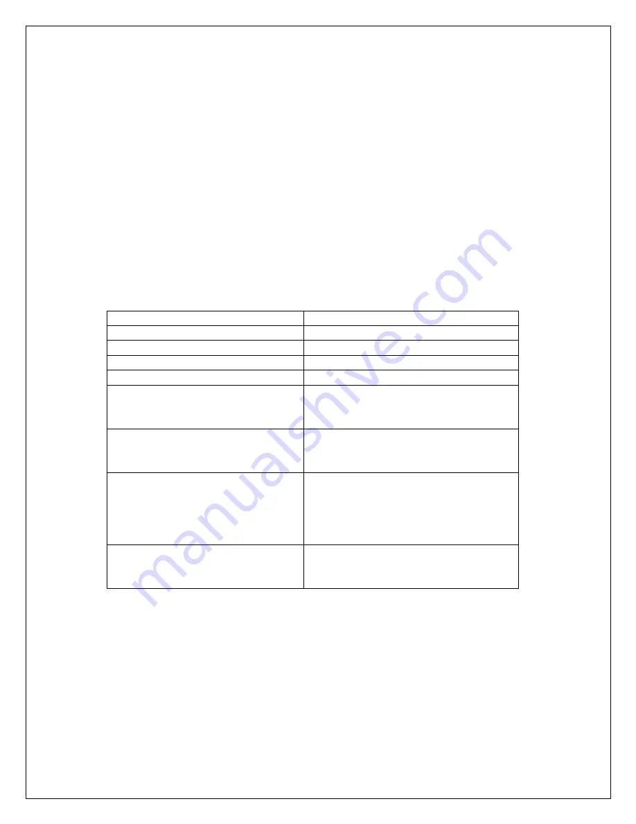
Table 1-1 Health and Safety Handling of R134a 


Allowable Overall Exposure Limit  1,000 ppm 
Vapor Exposure to Skin 

No Effect 

Liquid Exposure to Skin 

Can cause frostbite 

Vapor Exposure to Eyes 

Can cause very slight irritation 

Liquid Exposure to Eyes 

Can cause frostbite 

Above Minimum Exposure Limit 

Can cause asphyxiation, tachycardia 
and cardiac arrhythmia's. Wear 
appropriate skin and eye care. 

Spill Management 

Combustible sources. Evacuate or 
ventilate area. 
May decompose if in contact. 

Fire and Explosion Hazards 

Made with flames and heating 
elements. Container may explode if 
heated due to pressure rise. 
Combustion products are toxic. 
 

Storage Conditions 

The  procedures/rules for R12 also 
apply to R134a. 
Reclaim 


Содержание WINE-MATE VINO3500HZD

Страница 1: ...E MATE Cooling Unit Service Manual VINO 3500HZD VINO 4500HZD VINO 6500HZD VINO 8500HZD Vinotemp International Inc w ww ww w v vi in no ot te em mp p c co om m w ww ww w w wi in ne em ma at te e c co o...

Страница 2: ...1 SAFETY INFORMATION...

Страница 3: ...the Thermistor 10 6 Removing Fan Motors 10 7 Removing the Start Relay and Overload Protector 10 8 Removing the Compressor 11 9 Removing the Condenser 12 10 Removing the Evaporator 12 3 Servicing and D...

Страница 4: ...ce personnel will Fully understand the proper safety precautions Successfully install the cooling unit Successfully troubleshoot and diagnose malfunctions Successfully perform necessary repairs Succes...

Страница 5: ...will drive moisture back into sealed system Table 1 1 Health and Safety Handling of R134a Allowable Overall Exposure Limit 1 000 ppm Vapor Exposure to Skin No Effect Liquid Exposure to Skin Can cause...

Страница 6: ...ion and Access This section provides you the component information and access inside the cooling unit The components and their locations are shown Figures 2 1 through 2 11 below I Model Number Serial...

Страница 7: ...he Inner Styrofoam Once the outer cover is removed this will expose the inner styrofoam pieces The top large styrofoam seals off the condenser and evaporator fan compartments To gain access to the oth...

Страница 8: ...7 Figure 2 3 Figure 2 4...

Страница 9: ...5 3 Removing the Fan Plate 1 Disconnect the power cord compressor cord and temperature controller wires from the terminal block 2 Remove the 6 rivets on the front and rear sides 3 Remove the fan plate...

Страница 10: ...8 1 Unplug the cooling unit or disconnect power 2 Remove the outer cover 3 Remove all the lower side styrofoam pieces 4 Disconnect all the wires from the temperature controller 5 Press the 2 snappers...

Страница 11: ...e horizontal fan plate They are the same and all powered up at the same time 1 Unplug the cooling unit or disconnect power 2 Remove the outer cover 4 Remove all the upper and lower styrofoam pieces 5...

Страница 12: ...ng straight out away from the compressor terminal Figure 2 10 9 Removing the Compressor Figure 2 11 1 Unplug the cooling unit or disconnect power 2 Remove the outer cover 3 Remove all the upper and lo...

Страница 13: ...e all the upper and lower styrofoam pieces 4 Remove the fan plate 5 Place piercing valves onto the process tubes and discharge the refrigerant into an approved R134a recovery system 6 Use a tubing cut...

Страница 14: ...Figure 3 1A 3 button controller A Live Line 115VAC 60Hz red shrunk wire from the power line B Neutral Line white shrunk wire from the power line C Compressor Wires black shrunk wire from the compresso...

Страница 15: ...re from the power line C Compressor Wires black shrunk wire from the compressor terminal connecting the orange wire from the controller compressor output white shrunk wire from the compressor terminal...

Страница 16: ...the S terminal The ohmmeter shall show a reading of sum of the last two measurements If not the compressor is bad 8 Touch and hold one ohmmeter probe to the C or R or S terminal then touch and hold th...

Страница 17: ...ng 7 Turn the relay upside down 8 Place and hold the ohmmeter probe in one terminal and place the other ohmmeter probe in the other terminal The ohmmeter shall show zero resistance If not the start re...

Страница 18: ...nect the red and white wires connected to the input 7 and 8 of the temperature controller 3 Touch and hold one ohmmeter probe to one terminal on the temperature controller then touch and hold the othe...

Страница 19: ...r probe to the orange or black wire then touch the other probe to the white wire 8 Now the voltmeter shall read 115 volts 9 If the readings are both correct the electronic controller is good 6 Thermis...

Страница 20: ...turned on 2 Locate the black and white wires from the fan motor being tested and follow them back to the terminal block 3 Set the voltmeter to the AC 200 scale 4 Touch and hold one voltmeter probe to...

Страница 21: ...No power from supply c Incorrect or loose wirings d Low voltage e Setting higher than ambient temperature f Cut in too high g Defrost light blinking h Compressor light blinking i Defective controller...

Страница 22: ...perature ok c Failed controller and probe a Move the air probe away from the evaporator b Deflect the supply air down c Call service for diagnosis 6 Temperature high or not cooling and running continu...

Страница 23: ...nd overload protector b Check for condenser fan c Clean condenser d Call service for removing refrigerant e Call service for information 11 Fan running too long a Post compressor fan running mode for...

Страница 24: ...the drip tray 16 Circuit tripping a Incorrect fuse or breaker b Incorrect wirings c Failed components a Check for proper fuse or breaker b Check for wirings and connections c Call service 17 Noisy op...

Страница 25: ...24 4 Customer Support If you still have problems please contact us at Vinotemp International 17631 South Susana Road Rancho Dominguez CA 90221 Tel 310 886 3332 Fax 310 886 3310 Email info vinotemp com...

Страница 26: ...this warranty Service under Warranty This service is provided to customers within the continental UNITED STATES only VINOTEMP cooling units are warranted to produce the stated number of BTU H While e...

Страница 27: ...NTY IS EXCLUSIBE AND IS IN LIEU OF ALL OTHER WARRANTIES EXPRESSED OR INPLIED INCLUDING BUT NOT LIMITED TO IMPLIED WARRANTIES OF MERCHANTABILITY OR FITNESS FOR A PARTICULAR PURPOSE While great effort h...

Отзывы: