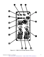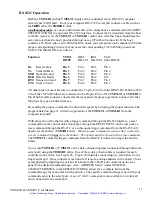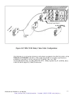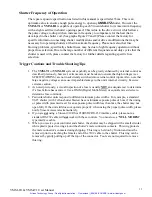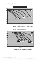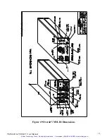
VMM-T1 Front Panel Operator Controls
Description
(Refer to Figure #3)
1.
DELAY
TIMER SELECT. Four pushwheel switches determine the DELAY timing range. The
total delay interval will be the product of the DELAY TIMER SELECT and DELAY
MULTIPLIER. (Each depression of the (+) key increases each digit by one, the (-) key
decreases each digit by one.)
2.
DELAY
LED indicator. LED indicates when DELAY timer is active.
3.
EXPOSURE
TIMER SELECT. Four pushwheel switches determine the EXPOSURE timing
range. The total exposure interval will be the product of the EXPOSURE TIMER SELECT and
EXPOSURE MULTIPLIER. (Each depression of the (+) key increases each digit by one, the (-
) key decreases each digit by one.)
4.
EXPOSURE
LED indicator. LED indicates when EXPOSURE timer is active.
5.
EXPOSURE
MULTIPLIER switch. Clockwise rotation of the 5 position rotary switch
increases the magnitude of the EXPOSURE interval by a factor of ten.
6.
EXP. PRESET
SELECT. Two pushwheel switches determine the number of exposure cycles
the unit will count up to per trigger input. A setting of “00” allows the unit to run continuously
until reset. In the “00” or continuous setting, the time between exposures is determined by the
DELAY time interval.
7.
SYNC. ACTIVE
Indicator. LED indicates the status of the Solid State Sync. system. LED is
illuminated when the shutter's electronic sync. is active. (This LED functions only if the
shutter used is equipped with the Solid State Sync. system.)
8.
DRIVER ACTIVE
Indicator. LED indicates when the internal shutter driver circuit input has
an active signal present.
9.
ACTUATE
Switch. Depress this momentary pushbutton switch to trigger the
VMM-T1
EXPOSURE and DELAY timers from the front panel.
10.
RESET
Switch. This momentary pushbutton switch inhibits all functions of the unit. Depress
this switch to reset both the EXPOSURE and DELAY timers, and return all outputs to their
original state. Shutter state will be returned to the status set by the N.O./N.C. switch.
Please
note if an open command is sent to the RS-232 input, a reset command will not clear the RS-
232 output and the shutter will not close. You must send a close command to allow the shutter
to close. If you wish to have the shutter close with a reset command or this RESET switch, you
must open the shutter with a trigger command. (The shutter will either close, upon reset, or
return to the state as set by the N.O./N.C. switch.)
11.
PRE/POST
Toggle Switch. Position of this switch determines if DELAY interval occurs
before (PRE) or after (POST) the EXPOSURE interval. The PRE position delays the start
of
the shutter EXPOSURE interval until the end of the DELAY interval. In the POST mode the
DELAY timer is triggered at the conclusion of the EXPOSURE interval. In PRE or POST the
DELAY (AUX) output will go high for the duration of the DELAY interval when the DELAY
timer is active, (the
VMM-T1
only).
12.
POWER
LED Indicator.
VMM-D1 & VMM-T1 User Manual
19
Artisan Technology Group - Quality Instrumentation ... Guaranteed | (888) 88-SOURCE | www.artisantg.com

