background image

Inst. and Maint. Manual | Oxeo PR LCP | F_101921 Rev 02 | 10-2022 | en

73

Old pipelines

Personnel:

Authorized Distributor

If old pipelines are used in the system, or if existing pipelines are used in the protected area, they 
must be checked before they are used.

1.    Pressure test the pipelines.
2.    Empty pipelines.
3.    Clean the pipelines.
4.    Let the pipelines dry

NOTICE   

Material damage due to unsuitable pipelines

If pipelines do not satisfy the requirements, there is a danger that they will fail when there 
is flooding.

Only use pipelines if they can withstand the required pressures.

Содержание Oxeo

Страница 1: ...Installation and Maintenance Manual Oxeo Inert Gas Extinguishing System...

Страница 2: ...e location and retained for future use This document is a translation of the original German document with modifications specific to the usage in North and South America The Viking Corporation 210 N I...

Страница 3: ...ent 16 2 8 Obligations of the Authorized Distributor 17 2 9 Safety and protective devices 18 2 10 Signage 20 2 11 Environmental protection 24 2 12 Behavior in the case of fire 24 3 Transport packaging...

Страница 4: ...y and installation 69 5 2 Requirements imposed on the pipeline system 71 5 3 Manifold Assembly 74 5 4 Extinguishing cylinder with quick release valve QRV 75 5 5 Installing the safety valve 90 5 6 Moun...

Страница 5: ...unction of QRV actuation 145 7 3 Checking the functioning of the pneumatic time delay 145 7 4 Checking the functioning of the makrofon MX 1 148 7 5 Establishing operational readiness 148 8 Inspection...

Страница 6: ...ns 182 12 Appendix A Racking Assembly 183 12 1 Introduction 183 12 2 Racking System Configurations and Ordering Information184 12 3 Spare parts and component technical data 187 12 4 Assembling the Rac...

Страница 7: ...Qualified knowledge of the extin guishing agent used and the technical details of Oxeo inert gas extinguishing systems Oxeo PR LCP with a pressure reducer are prerequisites for working with this manua...

Страница 8: ...ev 02 10 2022 en 2 Applicable documents Operating manual Oxeo inert gas extinguishing system with pressure reducer Oxeo PR LCP form no F_101821 Design manual Oxeo inert gas extinguishing system with p...

Страница 9: ...ion of the respective country of deployment Illustrations in this document are intended to facilitate basic understanding and may differ from the actual design of the product 1 3 Copyright Any content...

Страница 10: ...Inst and Maint Manual Oxeo PR LCP F_101921 Rev 02 10 2022 en 4...

Страница 11: ...ety and warning notices Safety and warning notices are marked with symbols in this document The introductory signal words express the respective extent of the danger DANGER The signal word describes a...

Страница 12: ...Unscrew screw 2 Carefully close the cover 3 Tighten screw 2 3 Intended use This system is designed exclusively for the intended use described here The Oxeo inert gas extinguishing system is intended o...

Страница 13: ...use the system in conjunction with the following fire hazards Chemicals that release oxygen Mixtures containing oxidizing substances e g sodium chlorate sodium nitrate explosives gunpowder Chemicals...

Страница 14: ...of operation without delay and secure against accidental commissioning Also observe the following Use only original spare and wear parts Replace parts that are not in perfect condition immediately Do...

Страница 15: ...notices as described in this document Demands on personnel as described in this document 2 5 General dangers The following section describes residual risks that can arise from the system even with pro...

Страница 16: ...Power down 2 Safeguard against restart 3 Ensure de energized state 4 Ground and short circuit 5 Cover or shield any adjacent live components Never remove safety devices change them or render them inop...

Страница 17: ...NG Risk of injury from cold extinguishing agent The extinguishing agent exiting at the discharge nozzles is very cold Direct contact may result in injury Leave the extinguishing zone without delay and...

Страница 18: ...y cause severe injuries and property damage Activate the system only in the event of a fire Protect the manual release devices in the protected enclosure from inadvertent activation Refrain from smoki...

Страница 19: ...directly into the discharge zone of the discharge nozzles WARNING Risk of injury from noise High sound pressure levels caused by discharged gas and acoustic alarm equipment e g signal horns may cause...

Страница 20: ...basic regulations on occupational safety and accident prevention They have been given instruction on handling the system The various tasks described in this document require that the persons responsi...

Страница 21: ...systems and independently detecting and avoiding any possible risks due to his her long years of expertise and experience and his her familiarity with all applicable standards and regulations A quali...

Страница 22: ...ead against falling objects hanging loads and bumping against stationary objects 2 7 3 Protective goggles Protective goggles cover the entire area of the eyes including the sides and are used to pro t...

Страница 23: ...tributor must Ensure that the system complies with the valid provisions and regulations for the installation of fire extinguishing systems with the extinguishing agent used in this system and that the...

Страница 24: ...aining The Authorized Distributor must instruct the owner or the person in charge of the system in the handling of the system and subsequently hand over the operating manual to this person For better...

Страница 25: ...the flow of extinguishing agent in the flow direction and prevent it in the opposite direction They are located at the transitions of the hoses to the manifold Pilot pressure relief device The pilot...

Страница 26: ...They are provided with vent bores in order to enable a controlled release of pressure in case of unintentional activation The locking nuts are connected to the valves by means of loss protection devi...

Страница 27: ...the containers from tipping over and falling down as well as from heating impact and shock 210 N INDUSTRIAL PARK DR HASTINGS MI 49058 USA PN 24588 9 40 0 This area is protected by a Viking Nitrogen f...

Страница 28: ...every pilot cylinder providing specific information about the container It contains the specifications listed below FIGURE 2 2 Type plate 1 Nominal pressure bar 2 Designation pilot cylinder 3 Pilot ga...

Страница 29: ...2022 en 23 Label for extinguishing agent container FM UL For FM UL each extinguishing agent container has an additional label with more specific informa tion It includes the following information FIGU...

Страница 30: ...ing first aid and rescue equipment as well as the possibilities for manually actuating the system Keep access roads for rescue vehicles clear Measures in the case of fire When the system alarm devices...

Страница 31: ...o danger posed to your own health rescue people from the danger zone Immediately leave the extinguishing zone Begin applying first aid measures if required Warn people who are in danger in adjacent ar...

Страница 32: ...Inst and Maint Manual Oxeo PR LCP F_101921 Rev 02 10 2022 en 26...

Страница 33: ...kages can have an eccentric center of gravity If attached incorrectly the package can tip over and fall Severe injuries or even death can result by falling or tipping packages When transporting with a...

Страница 34: ...to fatal injuries can occur Always transport extinguishing agent containers in compliance with the instructions contained in this manual Comply with locally valid regulations concerning transport of...

Страница 35: ...he blanking plugs are on the control output and the valve protection caps have been assembled Always secure the extinguishing agent containers in accordance with the following specifications WARNING R...

Страница 36: ...rdance with the valid local regulations for the transport of dangerous goods 1 Contact the local specialist for the transport of dangerous goods and inquire about the regulations on transporting extin...

Страница 37: ...pty extinguishing agent containers Extinguishing agent containers that have been activated contain a residual pressure of approx 22 psi 1 5 bar This residual pressure prevents dirt and moisture enteri...

Страница 38: ...e pressure gauge connection 3 Screw the valve protection cap onto the extinguishing agent container 3 2 2 Transporting pallets Transporting pallets with the fork lift Personnel Authorized Distributor...

Страница 39: ...er of gravity ensure that the pallet cannot tilt 4 Lift the pallet with the transport package and start the transport 3 3 Packaging About the packaging The individual packages are packed in boxes or c...

Страница 40: ...n the supplied pallet Observe national regulations on the storage of extinguishing agent cylinders If stored for more than 3 months regularly check the general condition of all extinguishing agent cyl...

Страница 41: ...other way which may result in risks no longer being detected and the necessary operating instructions no longer being followed This will lead to a risk of injury Keep all safety warning and operating...

Страница 42: ...Inst and Maint Manual Oxeo PR LCP F_101921 Rev 02 10 2022 en 36...

Страница 43: ...rofon and the non electrical time delay unit immediately Once the set delay time passes the extinguishing agent containers assigned to the extinguishing zone are opened pneumatically The extinguishing...

Страница 44: ...stem can also be activated manually using manual electric releases These releases are usually installed at the extinguishing zone access point For more details and information about the variants of th...

Страница 45: ...guishing agent con tainer master is actuated electrically in the same way as in single container systems and option ally also manually All other extinguishing agent containers slaves are opened pneuma...

Страница 46: ...ucer The selector valves and manifold pipes are also located in the high pressure pipework for multi zone systems Downstream pipework The area of the downstream pipework starts behind the pressure red...

Страница 47: ...g agent containers on the pipe net work Manifolds are intended for a one two or three row set up for extinguishing agent containers Manifolds with 2 to 3 inlets are available for the one two or three...

Страница 48: ...ick release valve QRV FIGURE 4 6 Extinguishing agent container and valve protection cap The extinguishing agent is stored in one or more extinguishing agent containers in a con tainer battery that is...

Страница 49: ...and can be opened pneu matically electrically or manually When the valve is open the extinguishing agent flows through the pipelines to the extinguishing nozzles The valve works according to the diff...

Страница 50: ...nt container is empty with the exception of the remaining residual pressure see below 4 6 2 Release device manual QRV FIGURE 4 8 Release device manual 1 Manual lever 2 Split pin 3 Release pin The rele...

Страница 51: ...device electrical QRV 1 Connector plug 2 Cable leading to control panel 3 Release device electrical QRV 4 Cylinder valve The release device electrical QRV with the connector plug activates the valve...

Страница 52: ...for the presence and correct assembly of the electrical release device on the QRV valve If the release device is present and correctly assembled the monitoring switch is activated If the release devic...

Страница 53: ...eck valve the contact pressure gauge can be assembled even if the extinguishing agent container is pressurized The automatic loss monitoring is set to a 10 pressure loss scale area marked in green bas...

Страница 54: ...ed for proper function seals are not included in the scope of delivery of the hose Both hoses come with gaskets 149890 and 149970 included Gaskets 149890 and 149970 can also be ordered as spare parts...

Страница 55: ...s The master slave combination is only used if no pilot cylinder is required and there are no life safety requirements Both connections have a thread of M12 x 1 5 and 24 sealing cone light series with...

Страница 56: ...available of the inlet and outlet connection threads are possible The pressure reducer is produced with conical inner thread in accordance with two different standards ISO 7 ANSI ASME B1 20 1 NPT The...

Страница 57: ...Inst and Maint Manual Oxeo PR LCP F_101921 Rev 02 10 2022 en 51 FIGURE 4 15 Pressure reducer 1 Inlet side 2 Outlet side FIGURE 4 16 Pressure reducer with sieve...

Страница 58: ...2 NPT 2 NPT with protective screen1 25013 Pressure reducer 2 NPT 2 NPT 2 25014 Pressure reducer 2 NPT 2 1 2 NPT with protective screen1 25015 Pressure reducer 2 NPT 2 1 2 NPT2 25016 Pressure reducer 2...

Страница 59: ...ures pressure relief A blow off line attached to the outlet on the safety valve leads the medium to safely discharge on the out side 4 12 Occupiable space protection kit FIGURE 4 18 Occupiable space p...

Страница 60: ...cal QRV part no 914027D 3 Pneumatic pilot line precision steel pipe 4 Monitoring of electric release device QRV The pneumatic control device is installed standing on the floor and fastened to a wall u...

Страница 61: ...e connected to a reserve pilot cylinder via a shut tle non return valve Pilot cylinder with wall support FIGURE 4 20 Pilot cylinder with unistrut racking 1 Protective cap 2 Locking nut 3 Pilot cylinde...

Страница 62: ...less fitted with a protective valve cap and locking nut on the valve output Filled pilot cylinders must be labeled and transported as hazardous material in accordance with all applicable local guideli...

Страница 63: ...F_101921 Rev 02 10 2022 en 57 Adapter and pressure reducer FIGURE 4 22 Adapter and pressure reducer 1 Adapter connection DN8 2 Pressure reducer The adapted connection DN8 adapts the valve thread to t...

Страница 64: ...gon socket secured with sealing wax 4 Threaded connection G1 8 5 Sinter filter Silencer 6 Factory set delay time 30 seconds A Pressure connection pneumatic pilot line coming from the pressure reducer...

Страница 65: ...has been given by the electric control device fire detection and suppression control panel the pilot cylinder is opened electrically without delay A pressure reducer downstream of the pilot cylinder r...

Страница 66: ...Silencer not included in the scope of delivery The makrofon is a pneumatically operated alarm device that is used in stationary gas extin guishing systems for life safety Membranes in the makrofon ar...

Страница 67: ...t A 2 Output 3 Input B The shuttle non return valve enables the differentiated triggering of a pneumatic assembly com ponents through two pressure sources By pressure at input A input B is closed and...

Страница 68: ...ressure relief device is used on the quick release valve QRV to prevent the down stream extinguishing agent containers from being incorrectly activated by such an uninten tional pressure build up Afte...

Страница 69: ...ables the discharge of small leaks in pneumatic pilot lines using a relief bore The pilot pressure relief device closes automatically at high pressures The pilot pressure relief device can only be ass...

Страница 70: ...m the rooms within the pre warning time the fire extinguishing system must be blocked The ball valve makes it possible to shut off the pilot line At the same time the shut off vents the onward pilot l...

Страница 71: ...gent pressure activates the cylinder which opens or closes the floating contacts of the limit switch FIGURE 4 29 Pneumatically operated limit switch part no 826758D 1 Pneumatically operated limit swit...

Страница 72: ...unit During activation the extinguishing agent flows through the nozzle expanding once it exits the nozzle bores The structure of the nozzle allows the flow determining component orifice to be adjuste...

Страница 73: ...se applications such as bag houses dust col lectors and machining centers 4 20 Pilot line made of precision steel pipe FIGURE 4 32 Pilot line made of precision steel pipe Pilot lines made of precision...

Страница 74: ...PR LCP F_101921 Rev 02 10 2022 en 68 Version Cut ring form A or B in accordance with DIN3861 or in accordance with DINENISO8434 1 Steel pipes in accordance with DIN2394 DINEN10305 test certificate in...

Страница 75: ...handling of the fire extinguishing systems described herein 5 1 Warnings for assembly and installation WARNING Danger of injury from faulty release A faulty release of the system may cause severe inju...

Страница 76: ...fety pins on components of the system only after complete assembly of the compo nents Block the system or parts of the system as needed Ensure that the valve output is always closed with a locking nut...

Страница 77: ...ts leak or fail due to improper pipe mounting this can cause failure of the system Thus if there is fire life threatening danger as well as significant material damage can occur Fit pipelines stress f...

Страница 78: ...m pressures Take pres sure hammers into account Select materials and diameters of pipelines in accordance with VdS2380 and ISO14520 and NFPA2001 and other locally applicable regulations Here special a...

Страница 79: ...ed in the protected area they must be checked before they are used 1 Pressure test the pipelines 2 Empty pipelines 3 Clean the pipelines 4 Let the pipelines dry NOTICE Material damage due to unsuitabl...

Страница 80: ...oning of the manifold is primarily based on the hydraulic calculation FIGURE 5 1 Manifold assembly 1 Bolt 2 Bracket 3 Manifold 1 Install the racking assembly brackets and cut an appropriate length of...

Страница 81: ...Distributor Protective equipment Safety gloves Safety footwear 5 4 1 Assembling extinguishing agent containers DANGER Risk of accidents due to heavy pressurized containers Extinguishing agent contain...

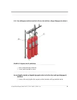
Страница 82: ...Manual Oxeo PR LCP F_101921 Rev 02 10 2022 en 76 FIGURE 5 2 Assembling extinguishing agent containers 1 Extinguishing agent container 2 Contact pressure gauge 3 Pilot pressure relief 4 Mounting bracke...

Страница 83: ...t containers using the valve output 5 Repeat the process for all extinguishing agent containers 6 Tighten all mounting brackets 5 4 2 Assembling the hose FIGURE 5 3 Assembling the hose onto the manifo...

Страница 84: ...valve output are correctly aligned with one another 6 Firmly tighten both union nuts of the hose using a suitable wrench without twisting the hose do not subject the hose to torsion 5 4 3 Mounting the...

Страница 85: ...e QRV 3 Pressure gauge connection connection thread M12 x 1 4 Plug 1 Remove the plug at the pressure gauge connection 2 Manually screw in the contact pressure gauge into the pressure gauge connection...

Страница 86: ...10 2022 en 80 3 If the contact pressure gauge is pressurized and is therefore more difficult to turn screw it on the size 14 flat with a suitable tool until it stops To align the contact pressure gaug...

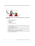
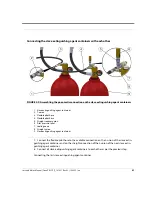
Страница 87: ...xtinguishing agent containers FIGURE 5 7 Alignment with installation 1 Master extinguishing agent container 2 Slave extinguishing agent container Connecting the master extinguishing agent container to...

Страница 88: ...ction and tighten with a torque of 12 x 1 Nm 8 85 x 0 74 ft lb 3 Remove the threaded plugs from the control connections for the quick release valves on the slave extinguishing agent container 4 Screw...

Страница 89: ...xible pilot hose 5 Straight reducer union 6 Pilot pressure relief 7 Sealing cone 8 Straight union 9 Slave extinguishing agent container 7 Connect the flexible pilot hose to the available connection on...

Страница 90: ...ed and free of contamination WARNING Risk of injury due to escaping extinguishing agent Assembly of the release device with a release pin in the activated position causes the quick release valve to op...

Страница 91: ...10 Remove protective caps 1 Plastic protective cap 2 Quick release valve QRV 3 Plastic protective cap 4 Release device 5 Plastic protective cap 3 Remove the plastic protective cap from the quick relea...

Страница 92: ...osition 2 Release pin indicator 3 Release pin in the activated position 5 Tension the activated release device as required WARNING Risk of faulty release Make sure that the release pin is in the not a...

Страница 93: ...lease device QRV 2 Release device 3 Quick release valve QRV 6 Screw the release device to the quick release valve QRV from above with 25 4 Nm 18 44 2 95 ft lb 7 It is also possible to screw the manual...

Страница 94: ...e electrical release device FIGURE 5 13 Attach limit switch 1 M4 x 30 cylinder bolts 2 Washers 3 QRV support bracket 1 Attach the limit switch to the holder QRV with two M4 x 30 cylinder bolts and two...

Страница 95: ...ing a pipe clamp QRV two M5 x 20 cylinder bolts and two washers 4 Position the limit switch on the electrical release device so that the limit switch actuates prop erly but does not exceed its maximum...

Страница 96: ...may impede the functioning of the safety valve This results in a risk of serious injury as well as substantial property damage The safety valve blow off line should be measured adequately taking into...

Страница 97: ...r 2 Seal ring 2 Push the seal ring onto the screw in connector of the safety valve 3 Screw the safety valve together with the seal ring into the intended component WARNING Risk of malfunctioning The s...

Страница 98: ...bling the blow off line 1 Outlet 4 Connect the blow off line de energized to the outlet of the safety valve 5 6 Mounting the pilot control cylinder For information regarding the installation of the pi...

Страница 99: ...g at the pressure gauge connection 6 Manually screw the contact pressure gauge into the pressure gauge connection M12 x 1 of the quick release valve until it can no longer be turned easily Only contac...

Страница 100: ...t pressure gauge 1 Size 14 flat 2 Proper positioning of flat 7 If the contact pressure gauge is pressurized and is therefore more difficult to turn screw it on the size 14 flat with a suitable tool un...

Страница 101: ...n to the pressure reducer 1 Adapter connection DN8 2 Pressure reducer 8 Screw the adapter connection DN8 onto the union nut of the pressure reducer using a size 19 flat wrench Assembling the pre assem...

Страница 102: ...e quick release valve using a size 30 flat wrench FIGURE 5 21 Protective caps and electrical release device 1 Quick release valve 2 Plastic protective cap 3 Connector plug 4 Electrical release device...

Страница 103: ...is in the deactivated position If necessary tension the activated elec trical release device The red marking on the release pin is visible in both the activated and deactivated position and is thus n...

Страница 104: ...emble the monitoring of the electrical release device see Assembling the monitoring of the electrical release device on page 88 15 Assemble the connector plug 5 7 Assembling the shuttle non return val...

Страница 105: ...allation positions of the shuttle non return valve WARNING Danger of malfunction and resulting injuries Make sure that the specifications on the marking on the shuttle non return valve correspond to t...

Страница 106: ...part of the building 3 Push the union nut and cutting ring of the shuttle non return valve onto the precision steel pipe 4 Insert the precision steel pipe into the cutting ring union of the shuttle n...

Страница 107: ...y goggles Safety gloves Safety footwear FIGURE 5 27 Mounting flexible pilot hose 1 Union nuts WARNING Danger due to contamination Contaminated pilot hoses can cause individual components to malfunctio...

Страница 108: ...g an open end wrench 5 9 Assembling the pilot pressure relief device Personnel Authorized Distributor Protective equipment Safety goggles Safety gloves Safety footwear Do not use additional sealant Do...

Страница 109: ...device Assembly in the pilot line 1 Connect the pilot pressure relief to the union NOTICE Property damage due to incorrect assembly Integrate the safety device upright at all times into the pilot lin...

Страница 110: ...ng the blocking device Personnel Authorized Distributor Qualified electrician Protective equipment Safety gloves Safety footwear 5 10 1Mounting holder FIGURE 5 29 Mounting blocking device holder 1 Cyl...

Страница 111: ...nection 4 Directional indicator 5 Blocking device connection 2 Screw blocking device with the included cylinder screws and hexagon nuts to the holder so that the marking of the flow direction correspo...

Страница 112: ...to the intended screw terminals and according to the wiring diagram 2 Close the selector valve and check the signaling from the limit switch to the fire alarm con trol panel Limit switches cylinder sc...

Страница 113: ...conjunction with the complete system Every devi ation of the system from the design calculation e g different nozzle holes can restrict the function of the pressure reducer This can lead to severe in...

Страница 114: ...ection of the pressure reducer FIGURE 5 32 Mounting pressure reducer 1 Nozzle pipe system 2 Pressure reducer 3 High pressure line 3 Mount the pressure reducer as connection of the high pressure line w...

Страница 115: ...Conformity mark 3 Manufacturer s mark 4 VdS type approval code 5 Delay time factory setting 6 Working pressure 7 Type designation 8 Serial batch number 1 Check whether the working pressure specified o...

Страница 116: ...URE 5 35 Assembling the time delay unit 1 Pressurized connection 2 Operating connection 3 Mounting bores 4 Firmly fix the time delay unit to the building in the correct installation position using the...

Страница 117: ...om the extinguishing agent container battery extinguishing agent container group 3 Venting with sinter filter silencer 5 13 Assembling the downstream pipework Personnel Authorized Distributor Protecti...

Страница 118: ...site must be tested with a thread gauge Only use the following sealing materials1 PTFE sealing tape Fermit sealing cord silicone free Loctite 55 sealing cord NOT silicone free Loctite AVX 586 adhesiv...

Страница 119: ...ssembling 1 Limit switch 2 Fittings 3 Fastening bores 4 Support 5 Cylinder 6 Button 7 Pressurized air connection 8 Pipeline 1 Screw the cylinder to the support using the two screws supplied 2 Fasten t...

Страница 120: ...e pressurized air connection 6 Tighten the union nuts 7 Create an electrical connection as per the connection plan see Pneumatically actuated limit switch on page 135 8 Press the button on the limit s...

Страница 121: ...or cover nozzles Do not undertake any structural changes in the protected enclosure that would affect the spray area of the nozzles CAUTION Risk of injury caused by nozzle parts during mounting Worki...

Страница 122: ...crew the nozzle body into the fitting NOTE Nozzle comes with all components assembled Mounting the DCM style nozzle with gasket optional The nozzle must be located 1 from the top of the enclosure in o...

Страница 123: ...lation 1 Mounting socket 2 Nozzle Type DCM 3 1 2 Galvanized Union 4 1 2 BSPT to 1 2 NPT Adapter 5 NPT Piping to bag house 6 Baghouse side wall 5 16 Mounting the pilot line made of precision steel pipe...

Страница 124: ...d thus also cause the whole system to malfunction This can cause serious injury or even death and may also cause substantial property damage Before assembly check all pneumatic pilot lines and pipelin...

Страница 125: ...Pipe Outer Diameter 0 24 inches 6 mm 0 39 inches 10 mm Straight minimum pipe length Hmin without bending 1 1 38 inches 2 35 mm 1 58 inches2 40 mm Minimum installation length Lmin 1 77 inches 45 mm 1 9...

Страница 126: ...urring pipe ends 3 Clean pipes properly with compressed air NOTICE Reduced service life and leaks from obliquely sawn pipe ends Check the right angles of the saw cut The angle tolerance is 0 5 NOTICE...

Страница 127: ...ads and cone 1 Union body 2 Lubricant 3 Union nut a thread union body b cone c thread union nut 4 Apply lubricant to the thread and cone of the union body as well as the thread of the union nut to ach...

Страница 128: ...rewing on the union nut by hand 1 Union body 2 Union nut 3 Pipe 7 Screw on the union nut and cut ring by hand until contact with the union body is felt WARNING Danger of a leaky connection from incorr...

Страница 129: ...with a marker FIGURE 5 51 Holding the union body in place with an open end wrench WARNING Danger of leaks or pipes slipping out from incorrect assembly Tighten the union nut max 1 5 rotations and hold...

Страница 130: ...erial 10 Check whether the band of cut material completely covers the front surface of the cut ring The assembly is correct if there is clearly visible cut pipe material FIGURE 5 53 Cut ring prior to...

Страница 131: ...he functionality of the makrofon is not ensured if the inside of the horn is contaminated as a result of the makrofon being mounted in an unsuitable position Mount the makrofon in such a way to ensure...

Страница 132: ...2 Makrofon 3 Large mounting bracket 4 Spring washers and nuts 5 Pneumatic connection 6 Adjustable bracket alignment 7 Counter nuts NOTICE Property damage due to disassembly of the horn The horn and ho...

Страница 133: ...the clamping bracket The sound pressure level is reduced 3 Screw on the makrofon to the large mounting bracket using the hexagon screw M6 x16 spring washers and nuts so that the sound outlet is direct...

Страница 134: ...Inst and Maint Manual Oxeo PR LCP F_101921 Rev 02 10 2022 en 128...

Страница 135: ...Inst and Maint Manual Oxeo PR LCP F_101921 Rev 02 10 2022 en 129 6 ElectricalConnectionsandTerminal Assignments...

Страница 136: ...only by qualified electricians If damage to the cable insulation is detected switch off the power supply immediately and replace the defective cables with identical new ones Before starting any work...

Страница 137: ...release system of the fire extinguishing system 2 Connect the limit switch according to the connection diagram 6 2 Monitor for the electrical release device Contact material Silver Contact type 1 Nor...

Страница 138: ...n switch Connection Terminals direct 6 3 Contact pressure gauge Contact material Gold plated Data Value Unit Switch voltage 4 5 24 VDC VAC Switch current 5 100 mA Maximum contact load 2 4 W 0 00322 hp...

Страница 139: ...ormally closed NC When no pressure exists on the contact pressure gauge the contacts are closed Normally open NO When no pressure exists on the contact pressure gauge the contacts are open Connection...

Страница 140: ...ntact type 1 normally open 1 normally closed Connection Terminals direct Data Value Unit Maximum switch voltage 500 V AC Switching current at 230 V AC 4 A Switching current at 500 V AC 1 A Maximum con...

Страница 141: ...rmally open adjustable Connection Terminals direct 6 6 Light barrier loss monitoring Data Value Unit Maximum switch voltage 400 V AC Switching current at 400 V AC 6 A Maximum contact load 500 W 0 6704...

Страница 142: ...FIGURE 6 7 Circuit diagram 1 Voltage supply for light barrier 2 DIP switch 3 Dark switching 4 Monitoring of supply voltage An external voltage supply of 12 15 24V is always required at terminal 1 With...

Страница 143: ...pes Only when using the FMZ4100 SUX50 module the short circuit plugs must be removed to connect the SUX50 module EoL End of Line end of line always between UL and UL FMZ 9 V line Z line 2 7V Z line 3...

Страница 144: ...Inst and Maint Manual Oxeo PR LCP F_101921 Rev 02 10 2022 en 138 FIGURE 6 8 Wiring diagram 1 Short circuit plug 2 Automatic 9V line 3 Z line...

Страница 145: ...1 Connection socket 2 Fitting for flexible metal cable conduit 3 Flexible metal cable conduit 4 Fitting for flexible metal cable conduit 5 Limit switch For monitored electrical circuits as per NFPA th...

Страница 146: ...without an alarm device 1 Fire detection and extinguishing control panel 2 Connection socket 3 Terminating resistor 4 Limit switches shown here the actuated limit switch with a mounted electrical rele...

Страница 147: ...m device 1 Fire detection and extinguishing control panel 2 Connection socket 3 Alarm device resistor 4 Terminating resistor 5 Limit switches shown here the actuated limit switch with a mounted electr...

Страница 148: ...Inst and Maint Manual Oxeo PR LCP F_101921 Rev 02 10 2022 en 142...

Страница 149: ...f commissioning With incorrect sequence of commissioning there is a danger of mistaken activation A faulty release of the system may cause severe injuries and property damage For the commissioning ini...

Страница 150: ...activation lines of electrical extinguishing control technology and check whether no control signals arise 4 Make sure that no undesired system states are present 5 Commission control and pilot cylind...

Страница 151: ...upply under 144 psi 1 Apply power to the electrical release device QRV to activate the device and pop the release pin into the active position 2 Use the reset tool to reset the release pin back into t...

Страница 152: ...7 2 Testing the time delay unit 1 Adjusting spindle 2 Test pressure gauge A Pressurized connection 1 Connect the test device for pneumatic actuation directly to the pressurized connection 1 on the tim...

Страница 153: ...as nitrogen 7 5bar 109 psi Check the pressure on the test pressure gauge Adjust the adjusting spindle until the required delay time is reached 6 Secure the adjusting spindle using sealing wax The perm...

Страница 154: ...ning of the makrofon MX 1 Protective equipment Hearing protection Makrofons are tested in the course of extinguishing zone activation When the selector valves are activated the makrofon is clearly aud...

Страница 155: ...se device is mounted with a torque of 25 4Nm 18 442 95ft lb 7 Check if the switch levers of the blocking devices are in the OPERATIONAL position and if the switch levers are secured with padlocks 8 Ch...

Страница 156: ...Inst and Maint Manual Oxeo PR LCP F_101921 Rev 02 10 2022 en 150...

Страница 157: ...NG Risk of death due to missing fire protection There is limited or no fire protection when decommissioning the system Fires can cause serious injury or even death and substantial property damage Keep...

Страница 158: ...f components were replaced carry out the installation according to the specifications in this ser vice manual Reinstall all the fixing elements and observe the specified screw tightening torques Make...

Страница 159: ...st once Comprehensive servicing includes the following steps in addition to the full system test proper log in log off of work with the operator checking of the system specifics and changes and compar...

Страница 160: ...Inst and Maint Manual Oxeo PR LCP F_101921 Rev 02 10 2022 en 154 FIGURE 8 1 Example of an overview of a fire extinguishing system...

Страница 161: ...tainers main and reserve x Malfunction pressure safety device SFD 300 creeping gas assurance x Time delay unit TDU 10 u x x EPU 1 triggering of pneumatic activation elements x EPU 1 disable device x x...

Страница 162: ...In the event of a claim undocumented deviations from the original or maintenance may represent a high risk with regard to a clear issue of liability For this reason seam less documentation throughout...

Страница 163: ...System marking Markings in the protection zone for escape routes etc Authorized Distributor Checking activation and shut off for alarms with a manual release Authorized Distributor Checking activatio...

Страница 164: ...act pressure gauges Authorized Distributor Checking pipelines and discharge nozzles Authorized Distributor Checking the fire detection and extinguishing control panel Condition Proper connection Elect...

Страница 165: ...be announced in advance and prepared for Inform the operator of the pending servicing in advance Inform the operator that the automatic relaying of alarms must be deactivated for the time of the serv...

Страница 166: ...ishing agent containers or remove the pilot lines depending on the valve type Secure the pilot cylinder against faulty release e g unscrew the valve lever on the valve of the pilot cylinder or unscrew...

Страница 167: ...trol panel is not exposed to any damaging environmental influences 8 Check that the nameplates of the components are present and in clearly legible condition and that the emergency service sticker is...

Страница 168: ...perature Rated filling pressure Pressure with 10 loss F C psi bar psi bar 4 20 3539 244 3176 219 5 15 3655 252 3278 226 14 10 3771 260 3394 234 23 5 3887 268 3495 241 32 0 4003 276 3597 248 41 5 4119...

Страница 169: ...ciently ventilated to ensure that the maximum permissible extinguishing agent concentration NOAEL is not exceeded when the extinguishing agent is unintentionally released WARNING Risk of injury due to...

Страница 170: ...ly with the locally applicable guidelines e g NFPA2001 ISO17025 During the filling process the pressure gauge attached to the extinguishing agent container must not be used to determine when the inten...

Страница 171: ...G Risk of malfunctioning Improper replacement of components can result in malfunctions and thus prevent triggering of the fire extinguishing system in the event of a fire This can cause serious injury...

Страница 172: ...least one extinguishing agent container is leaky Identify the extinguishing agent container Person in charge of system See above Replace the extinguishing agent container immediately Authorized Distr...

Страница 173: ...m See above Replace the pressure gauge Authorized Distributor The value indicated on the contact pressure gauge is too low Extinguishing agent loss is less than 10 Compare the indicated value with the...

Страница 174: ...ure reducer A foreign object or dirt is blocking the inlet to the pressure reducer Check the connection components adapter valve output clean and remount if necessary Authorized Distributor No pressur...

Страница 175: ...does not open in spite of pneumatic actua tion valve defective or contaminated Replace time delay unit Authorized Distributor Fault description Cause Remedy Personnel Limit switch does not switch Limi...

Страница 176: ...Inst and Maint Manual Oxeo PR LCP F_101921 Rev 02 10 2022 en 170...

Страница 177: ...hreatening danger due to electric shock There is a life threatening hazard when touching live components Prior to dismantling switch off the electrical supply and definitively disconnect it WARNING Li...

Страница 178: ...ourse of disassembly extinguishing agent can escape uncontrolled This can lead to severe injuries or even death as well as significant property damage Prior to starting the tasks for which a faulty re...

Страница 179: ...ders up to the end of the extinguishing agent container batteries 5 Disassemble all system components in accordance with locally applicable occupational health and safety and environmental protection...

Страница 180: ...1 Removing the electrical release device 1 Electric release device QRV 2 Electrical release monitoring 3 QRV valve 1 Remove the monitoring of the electrical release device 2 Remove the electrical rel...

Страница 181: ...Manual Oxeo PR LCP F_101921 Rev 02 10 2022 en 175 FIGURE 10 2 Assembling the plastic protective cap 1 Plastic protective caps 3 Place plastic protective caps onto the valve and onto the electrical rel...

Страница 182: ...ugs into all sequence valve connections and control connections and tighten with a torque of 12 1 Nm 8 85 0 74 ft lb 6 Remove the electrical connections for the contact pressure gauge 7 Release the co...

Страница 183: ...Inst and Maint Manual Oxeo PR LCP F_101921 Rev 02 10 2022 en 177 FIGURE 10 4 Removing the hoses 1 Hose 9 Unscrew the hoses from the valves Store the seals in a safe place...

Страница 184: ...IGURE 10 5 Screwing on the union nuts 1 Valve outputs 2 Union nuts 10 Immediately screw union nuts onto all valve outputs with a torque of 35 Nm 26 ft lb FIGURE 10 6 Valve protection cap example 11 Sc...

Страница 185: ...side 13 Fasten the extinguishing agent containers standing up in a suitable transport frame or lying down on a pallet and secure against sliding 14 If required assemble filled extinguishing agent cont...

Страница 186: ...tion Safety gloves Safety footwear At the end of the equipment s service life dispose of it in accordance with legal regulations or through the national recycling system NOTICE Danger to the environme...

Страница 187: ...nt containers FM Approval requirements 32 131 0 55 F C Permitted temperature for transport storage of extinguishing agent containers FM Approval requirements 4 131 20 55 F C Permitted temperature in e...

Страница 188: ...ns Noise emission on activation Specification Value Unit Noise emission of pneumatic alarm device makrofon 1 approx 106 dB A 1The specified value is based on measurements in a laboratory with CO2 and...

Страница 189: ...n manual and the operation manual These documents and be found on the Viking website 12 1 Introduction The Oxeo support and racking system is ordered and delivered separately from the system The speci...

Страница 190: ...3 Back to back floor mount Each type can be customized however the systems are limited to 3 rows with a maximum of 18 cylinders per row To order a pre configured racking system use the information in...

Страница 191: ...1 18 24218 1 15 24219 1 12 24220 1 9 24221 1 6 24222 1 3 24210 2 18 24211 2 15 24212 2 12 24213 2 9 24214 2 6 24215 2 3 24224 3 18 24225 3 15 24226 3 12 24227 3 9 24228 3 6 24229 3 3 Part number Cyli...

Страница 192: ...8 3 6 24289 3 3 Part number Cylinder rows Width cylinders 24266 1 18 24267 1 15 24268 1 12 24269 1 9 24270 1 6 24271 1 3 24252 2 18 24253 2 15 24254 2 12 24255 2 9 24256 2 6 24257 2 3 24259 3 18 24260...

Страница 193: ...5 8 x 12 12 gauge HSLAS Gr 45 Electrogalvanized steel per ASTM B633 SC1 Type III 24126 Unistrut cantilever bracket 1 5 8 x 1 5 8 x 18 24127 Unistrut cantilever bracket 1 5 8 x 1 5 8 x 24 B 24128 Wolf...

Страница 194: ...LAS Gr 45 Electrogalvanized steel per ASTM B633 SC1 Type III G 24142 Brace 1 5 8 x 18 24141 Brace 1 5 8 x 24 H 24158 End cap 1 5 8 x 1 5 8 Vinyl I 24157 End cap double 1 5 8 x 3 1 4 Ref Part Number re...

Страница 195: ...5 8 x 181 24649 21650 Unistrut channel 1 5 8 x 1 5 8 x 216 1 2 24649 24000 Unistrut channel 1 5 8 x 1 5 8 x 240 L1 24650 00400 Threaded rod 1 2 13 X 4 Steel per ASTM F1554 20 Gr 36 Electrogalvanized...

Страница 196: ...osed V 24204 Cylinder brace assembly 2 row x 2 cylinder closed W 24203 Cylinder brace assembly 2 row x 3 cylinder open X 24202 Cylinder brace assembly 2 row x 3 cylinder closed Y 24201 Cylinder brace...

Страница 197: ...lts The break off bolts include a hexagonal head on top of the square head that is designed to break off a specific torque value Once head is broken off the bolt is properly tight ened Cylinder web cl...

Страница 198: ...nt versions do not require base supports FIGURE 12 3 Assembling the upright supports Unless explicitly instructed it is recommended to install all components loosely at first adjust as necessary to ac...

Страница 199: ...pright post 2 Drill pilot holes for the concrete anchors wall or floor depending on your system 3 Install the upright post using the concrete anchors P wall or M floor wolf washers B and the included...

Страница 200: ...ug the break off bolt in place but do not break it off FIGURE 12 5 Locating the horizontal support brackets 5 For floor mount versions loosely install floor brace using the retaining nut D wolf washer...

Страница 201: ...d loosely install it in the appropriate loca tion NOTE Do not anchor this post in place yet 1 FIGURE 12 7 Installing the opposite end support 7 Install the horizontal cross piece into the Z brackets a...

Страница 202: ...to assemble as described below Cantilever Brackets 1 Cut the rubber to length if necessary and place it inside the clamp if desired or set aside for later installation install the bolt and nut 2 Slid...

Страница 203: ...ross piece for the first threaded rod to ensure proper alignment 3 Install two nuts onto the threaded rod facing opposite each other as shown 4 Install the threaded rod into the retaining nut D 5 Tigh...

Страница 204: ...her bracket Continue installing brackets down the line skipping one span each time FIGURE 12 11 Cylinder bracket installation 1 11 Install the remaining bracket J in the open span s FIGURE 12 12 Cylin...

Страница 205: ...kets in the manner described above and alternating orientations to sup port the cylinders as shown below FIGURE 12 13 Fully assembled racking unit Refer to Chapter 5 for instructions regarding manifol...

Страница 206: ...Inst and Maint Manual Oxeo PR LCP F_101921 Rev 02 10 2022 en 200...

Страница 207: ...01030 Tank assembly OXEO 80 L 300 bar Nitrogen 4001050 Tank assembly OXEO 80 L 200 bar Argon Canada 4001024C Tank assembly OXEO 80 L 200 bar Nitrogen Canada 4001044C Tank assembly OXEO 80 L 300 bar Ar...

Страница 208: ...gas discharge hose to manifold 149890 Gasket inert gas tank to discharge hose 149970 Pressure gauge 2901 psi NO under pressure 927612 Pressure gauge 2901 psi NC under pressure 927615 Pressure gauge 43...

Страница 209: ...2 1 2 NPT 25016 Pressure reducer 2 NPT 3 NPT with protective screen 25017 Pressure reducer 2 NPT 3 NPT 25018 Adapter male 3 4 BSPP x male 3 4 BSPT single tank systems only 887706 Pneumatic limit swit...

Страница 210: ...2 NPT VN Nozzles 180 Style 0 378 934164D 0378 1 2 NPT VN Nozzles 180 Style 0 394 934164D 0394 1 2 NPT VN Nozzles 180 Style 0 413 934164D 0413 1 2 NPT VN Nozzles 180 Style 0 433 934164D 0433 1 2 NPT V...

Страница 211: ...2 NPT VN Nozzles 180 Style 0 362 918745D 0362 1 2 NPT VN Nozzles 180 Style 0 378 918745D 0378 1 2 NPT VN Nozzles 180 Style 0 394 918745D 0394 1 2 NPT VN Nozzles 180 Style 0 413 918745D 0413 1 2 NPT V...

Страница 212: ...8746D 0551 3 4 NPT VN Nozzles 360 Style 0 571 918746D 0571 3 4 NPT VN Nozzles 360 Style 0 591 918746D 0591 3 4 NPT VN Nozzles 360 Style 0 610 918746D 0610 3 4 NPT VN Nozzles 360 Style 0 630 918746D 06...

Страница 213: ...0 Style 0 866 934167D 0866 1 1 4 NPT VN Nozzles 180 Style 0 906 934167D 0906 1 1 4 NPT VN Nozzles 180 Style 0 945 934167D 0945 1 1 4 NPT VN Nozzles 180 Style 0 984 934167D 0984 1 1 4 NPT VN Nozzles 18...

Страница 214: ...zles 360 Style 1 024 918749D 1024 1 1 2 NPT VN Nozzles 360 Style 1 063 918749D 1063 1 1 2 NPT VN Nozzles 360 Style 1 102 918749D 1102 1 1 2 NPT VN Nozzles 360 Style 1 142 918749D 1142 1 1 2 NPT VN Noz...

Страница 215: ...2 DCM Nozzle 0 189 23379 0189 1 2 DCM Nozzle 0 197 23379 0197 1 2 DCM Nozzle 0 209 23379 0209 1 2 DCM Nozzle 0 220 23379 0220 1 2 DCM Nozzle 0 232 23379 0232 1 2 DCM Nozzle 0 244 23379 0244 1 2 DCM N...

Страница 216: ...591 24245 0591 3 4 DCM Nozzle 0 610 24245 0610 3 4 DCM Nozzle 0 630 24245 0630 3 4 DCM Nozzle 0 650 24245 0650 3 4 DCM Nozzle 0 669 24245 0669 DCM Nozzle 1 2 dust seal gasket 24454 DCM Nozzle 3 4 dus...

Страница 217: ...24649 18100 Unistrut channel 15 8 x 15 8 x 2161 2 24649 21650 Unistrut channel 15 8 x 15 8 x 240 24649 24000 Threaded rod 1 2 13 x 4 24650 00400 Threaded rod 1 2 13 x 121 2 24650 01250 Threaded rod 1...

Страница 218: ...22 en 212 Designation Part number Cylinder brace web assy 3 row x 1 cylinder closed 24201 Cylinder brace web assy 3 row x 2 cylinder closed 24200 Cylinder brace web assy 3 row x 3 cylinder open 24199...

Страница 219: ...checklists can be requested from the manufacturer for example regard ing Structural requirements that have an influence on the functionality and effectiveness of fire extinguishing systems Organizatio...

Страница 220: ...Inst and Maint Manual Oxeo PR LCP F_101921 Rev 02 10 2022 en 214...

Страница 221: ...Oxeo PR LCP 10 2022 en 215 15 SafetyDataSheet IG 01 Argon...

Страница 222: ...pictograms GHS US Signal word GHS US Warning Hazard statements GHS US H280 Contains gas under pressure may explode if heated May displace oxygen and cause rapid suffocation Precautionary statements GH...

Страница 223: ...ighting measures 5 1 Suitable and unsuitable extinguishing media Suitable extinguishing media Use extinguishing media appropriate for surrounding fire 5 2 Specific hazards arising from the chemical Fi...

Страница 224: ...proof equipment with flammable materials Ensure adequate ventilation especially in confined areas 8 3 Individual protection measures Personal protective equipment Personal protective equipment symbol...

Страница 225: ...ity and reactivity 10 1 Reactivity No dangerous reactions known under normal conditions of use In a fire or if heated a pressure increase will occur and the container may burst 10 2 Chemical stability...

Страница 226: ...SECTION 13 Disposal considerations 13 1 Disposal methods Waste treatment methods Do not discharge to public wastewater systems without permit of pollution control authorities No discharge to surface w...

Страница 227: ...r pressure 15 2 International regulations No additional information available 15 3 US State regulations Component State or local regulations Argon 7440 37 1 U S New Jersey Right to Know Hazardous Subs...

Страница 228: ...Oxeo PR LCP 10 2022 en 222...

Страница 229: ...Oxeo PR LCP 10 2022 en 223 16 SafetyDataSheet IG 100 Nitrogen...

Страница 230: ...zard pictograms GHS US Signal word GHS US Warning Hazard statements GHS US H280 Contains gas under pressure may explode if heated May displace oxygen and cause rapid suffocation Precautionary statemen...

Страница 231: ...re fighting measures 5 1 Suitable and unsuitable extinguishing media Suitable extinguishing media Use extinguishing media appropriate for surrounding fire 5 2 Specific hazards arising from the chemica...

Страница 232: ...proof equipment with flammable materials Ensure adequate ventilation especially in confined areas 8 3 Individual protection measures Personal protective equipment Personal protective equipment symbol...

Страница 233: ...information available SECTION 10 Stability and reactivity 10 1 Reactivity No dangerous reactions known under normal conditions of use In a fire or if heated a pressure increase will occur and the con...

Страница 234: ...duct SECTION 13 Disposal considerations 13 1 Disposal methods Waste treatment methods Do not discharge to public wastewater systems without permit of pollution control authorities No discharge to surf...

Страница 235: ...nternational regulations No additional information available 15 3 US State regulations Component State or local regulations Nitrogen 7727 37 9 U S Massachusetts Right To Know List U S New Jersey Right...

Страница 236: ...Oxeo PR LCP 10 2022 en 230...

Страница 237: ......

Страница 238: ...The Viking Corporation 210 N Industrial Park Dr Hastings MI 49058 USA Phone 269 945 9501 Fax 269 818 1680 www vikinggroupinc com...

Отзывы: