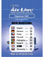
background image

PUSH FOR

VIKING

©

HELP

MODEL E-1600A-TP

EMERGENCY

PHONE

 CONNECTED

CALL

"Call Connected" LED

Push for "Help" Button ("Info" Button
available on model E-1600A-TP2-EWP)

Marine grade 316 stainless steel faceplate
and push button switch (sealed per IP67)

Grade 2 Braille Label

(6) 0.250 diameter counter sunk 82° x 0.410
diameter holes for flathead #10 x 24 
tamper-proof screws (not included)

7.750

4.00

2.75

9.50

10.250

0.875

11.75

5.125
 Typ

0.75

4.50

2.125

2.75

0.75

Minimum Cutout

5.125

S1

1

2

ON

3

11

10

9

8

7

6

5

4

3

2

1

Rear View of the

E-1600A-TP-EWP Phone Panel

Ring Connector
(included)

* Earth Ground

(optional)

1600A Emergency

Phone Board

LDB-3 Control 

Module

** Gel-Filled Butt

Connectors (included)

Note: Polarity Sensitive!

(-) Black with 

White stripe

120V AC

(+) Red with
Black stripe

(+) Black 

Red (+)

Black (-)

Green with Yellow stripe

Red with Yellow stripe

Auxiliary
Contact Output

Blue

Blue

Incoming

Analog Phone 

Line

Disable Feature
(see Programming section F)

Purple

Orange

Yellow

N.C.

COM.

N.O.

12V DC

Adapter

Included

(-) Black with 

White stripe

Positions 3 and 4 come factory 
wired directly to the 1600A 
Emergency Phone Board

Red

Green

*** Drip

Loop

*** Drip Loop

S1

1

2

ON

3

11

10

9

8

7

6

5

4

3

2

1

Switched 12VDC (350mA 
maximum) Output

I

I

n

n

s

s

t

t

a

a

l

l

l

l

a

a

t

t

i

i

o

o

n

n

A. Wiring

IMPORTANT:

Electronic devices are susceptible to lightning and power station electrical surges from both the AC outlet and the telephone line.  It is recommended

that a surge protector be installed to protect against such surges.  

!

(+) Black

(-) Black with

White Stripe

Step 1.

Step 2.

Step 3.

IMPORTANT: 

Do 

NOT

 plug in the

adapter until after 

Step 3

 is completed.

Step 1.

  Cut off the barrel connector.

Step 2.

  Seperate the wires.

Step 3.

  Connect 12V adapter wires to power supply wires

              on the 

LDB-3

 Control Module using the supplied 

              butt connectors and then plug in power supply.

Preparing the Power Supply

Connect power supply 

wires to 

LDB-3

 module 

power supply wires

B. Mounting

* Note:

To increase surge protection, loosen the PCB mounting screw labeled        (as shown) and fasten a wire with ring connector (included) from the

mounting screw to Earth Ground (grounding rod, water pipe, etc.)

** Note:

The gel-filled (water-tight) butt connectors are designed for insulation displacement on 19-26 gauge wire with a maximum insulation of 0.082 inch-

es. Cut off bare wire ends prior to terminating.

*** Note: 

When wires are routed from above, a “drip loop” is recommended to keep water away from the circuit board.

3

Содержание E-1600A-TP-EWP

Страница 1: ...with gel filled butt connectors Campus Security Sites Area of Refuge sites Parking Ramps Lots Automated Tellers ATM Entryways Roadside Emergency Sites Stairwells in Public Buildings TECHNICAL TECHNICA...

Страница 2: ...e to radio communications Operation of this equipment in a residential area is likely to cause harmful interference in which case the user will be required to correct the interference at his own expen...

Страница 3: ...Drip Loop Drip Loop S1 1 2 ON 3 11 10 9 8 7 6 5 4 3 2 1 Switched 12VDC 350mA maximum Output I In ns st ta al ll la at ti io on n A Wiring IMPORTANT Electronic devices are susceptible to lightning and...

Страница 4: ...de ring detection MUST be enabled DIP switch 1 ON C Relay Contacts Normally open and normally closed relay contacts are available on the orange purple and yellow wires The contacts are rated at 5A 125...

Страница 5: ...ts 0 20 digits 0 20 digits 0 20 digits 0 20 digits 0 20 digits 0 20 digits 6 digits 6 digits 6 digits 0 20 digits 0 20 digits QQ Q Q7 Q6 no digits Q0 7 00 01 02 03 04 05 06 07 08 09 17 18 19 20 21 00...

Страница 6: ...Q6 3 3 3 4 4 4 4 0 8 0 0 Step 1 See Section A Enter Programming Enter Programming Enter Programming 2 INFO Speed Dial Numbers E 1600A TP2 EWP only memory locations 07 09 The information speed dial num...

Страница 7: ...o Digit Announcement Delay Repeat Announcement Setting Hang up on Return to Dial Tone Panasonic Mode Lap Counter Enter Settings Here A B C D E F 17 If enabled and a busy is detected the 1600A series p...

Страница 8: ...ies phone with a Touch Tone phone and access programming Step 2 Enter Q4 wait for the tone and then begin recording Sixteen seconds of record time is available Step 3 Enter any Touch Tone to stop the...

Страница 9: ...count code and alarm details K Central Station Programming Microphone Sensitivity Speaker Volume ON OFF ON OFF 1 2 3 A B J DIP Switch Programming Speaker and Microphone Adjustments Two POTs are provid...

Страница 10: ...and if no answer then dial the central station receiver When calling the first numbers memory posi tions 00 04 see Programming section D the phone stays in two way talk mode allowing two way con versa...

Страница 11: ...voice announcement or by decoding the touch tone I D number Once the Call Connected LED is on the key can be used to force the phone to hang up O Op pe er ra at ti io on n 2 INFO Button E 1600A TP2 EW...

Страница 12: ...ed after the fourth attempt the 1600A hangs up and dials position 05 again 3 The 1600A has the capability to send a second informational message to the receiver after the first kiss off is received bu...

Отзывы: