manualshive.com logo in svg
background image

16

KICKPLATE INSTALLATION

The kickplate consists of a two (2) part assembly:  one top louvered panel and one bottom solid panel.  Install the
kickplate with louvered section on the top.  Flooring must allow the kickplate to be removed.  See “Site Preparations”
for height clearance (page 3).

To install:
1.  Insert the bottom (solid) panel into the open end of the top (louvered) panel.  The holes in the bottom panel should

line up with the slots in the top panel.

2.  Position the kickplate assembly along the front edge of the wine cellar.
3.  Align the holes on both ends of the top (louvered ) panel with the holes in the base of the wine cellar.
4.  Attach the kickplate to the wine cellar on each side with the two black phillips head screws provided.
5.  Adjust the bottom (solid) panel to the desired height and fasten in place by tightening the screws in the slots.

There is approximately 1” (2.5 cm) of vertical adjustment on the kickplate.

A

Attttaacch

h  tto

o  u

un

niitt  w

wiitth

h  tth

he

esse

e  ssccrre

ew

wss

S

Sccrre

ew

wss  aan

nd

d  ssllo

ottss

ffo

orr  aad

djju

ussttm

me

en

nttss

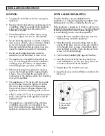
DOOR STOP ADJUSTMENT

1.  Using a 3/16” allen wrench, remove door stop pin

located in bottom hinge.

2.  The pin is factory set 110

o

.  For 120

o

swing, move the

pin to the utmost forward stop hole.  For 90

o

swing,

move the pin to the utmost rear stop hole.

HINGE ADJUSTMENT

1.  Using a 3/16” allen wrench, remove the door stop

pin located in bottom hinge.

2.  Using the height adjustment shim as a wrenching

device, rotate the height adjustment bushing
counterclockwise to raise or clockwise to lower the
location of the door.

3.  When proper adjustment is reached, align shim with

door stop pin holes and replace door stop pin.
Firmly tighten pin in place.

120

o

door stop

90

o

door stop

Содержание vcwb300

Страница 1: ...o or r m mo or re e p pe eo op pl le e t to o m mo ov ve e a an nd d i in ns st ta al ll l w wi in ne e c ce el ll la ar r F Fa ai il lu ur re e t to o d do o s so o c ca an n r re es su ul lt t i in...

Страница 2: ...ide trim 22 3 16 56 4 cm To front of top grille 24 1 2 62 2 cm To end of handle bracket 27 68 6 cm Cutout Width 29 1 2 74 9 cm Cutout Height 82 7 8 210 5 cm min 84 1 16 213 5 cm max Cutout Depth 24 61...

Страница 3: ...ficient and UV resistant glass doors 6 Low intensity lighting 7 Black interior 8 High temperature alarm behind grille 9 Door alarm behind grille 10 Connection to home security system behind grille 11...

Страница 4: ...OPENING DIMENSIONS 8 84 4 1 1 1 16 6 2 21 13 3 5 5 c cm m m ma ax x a an nt ti i t ti ip p b bo oa ar rd d a an nd d o op pe en ni in ng g h he ei ig gh ht t 8 82 2 7 7 8 8 m mi in n 2 21 10 0 5 5 c...

Страница 5: ...ut tl le et t D DO O N NO OT T r re em mo ov ve e g gr ro ou un nd d p pl lu ug g D DO O N NO OT T u us se e a an n a ad da ap pt te er r D DO O N NO OT T u us se e a an n e ex xt te en ns si io on n...

Страница 6: ...o B BA AC CK KW WA AR RD D T TI IP PP PI IN NG G R RA AD DI IU US S 51 7 8 131 8 cm 50 1 2 128 2 cm 48 5 8 123 5 cm 11 1 2 29 2 cm 15 1 2 39 4 cm S SI ID DE E T TI IP PP PI IN NG G R RA AD DI IU US S...

Страница 7: ...WINE CELLAR OVERALL DIMENSIONS 7 82 7 8 210 5 cm min to 84 1 16 213 5 cm...

Страница 8: ...m into the room 29 1 2 90 2 cm Wall 29 1 2 90 2 cm Wall 24 61 0 cm Standard cabinet depth 3 4 1 9 cm Full end panel 24 61 0 cm Standard cabinet depth 3 4 1 9 cm Full end panel 1 13 16 4 6 cm 2 5 16 5...

Страница 9: ...C C C C D DE ET TA AI IL L C C C C 29 1 2 90 2 cm Wall 24 61 0 cm Standard cabinet depth 3 4 1 9 cm Full end panel DOOR 1 13 16 4 6 cm space if 24 61 0 cm standard cabinet depth used 2 5 16 5 9 cm Off...

Страница 10: ...0 5 5 c cm m t to o 8 84 4 1 1 1 16 6 2 21 13 3 5 5 c cm m D De ep pe en nd di in ng g o on n h ho ow w h hi ig gh h l le ev ve el li in ng g f fe ee et t a ar re e r ra ai is se ed d a an nd d c ca a...

Страница 11: ...lternative wood facings NOTE A scrap sample should be tested in the unit before attaching permanent changes to your wine cellar fronts Some paints and or stains can cause undesirable odors Remove the...

Страница 12: ...ure 1 2 Remove top cap see Figure 1 3 Cut carton rear approximately 1 4 64 cm to 1 2 5 cm from right corner see figure 2 with a utility knife extended 1 4 6 cm Remove carton and exterior packaging Sav...

Страница 13: ...embly to the mounting brackets 5 Remove the 3 screws at the right side of the unit that attach the safety grille to the compartment cover 6 Choose the desired switching position and connect according...

Страница 14: ...5 cm into each of the two wall studs The wood block must extend a minimum of 3 7 6 cm over the unit To secure the wine cellar raise unit until compartment is firmly seated under the anti tip boards E...

Страница 15: ...r Push cardboard back with wine cellar and remove cardboard when wine cellar is in place 4 Lift the wine cellar off the rollers adjust to desired height and level wine cellar by using a 5 16 hex head...

Страница 16: ...height and fasten in place by tightening the screws in the slots There is approximately 1 2 5 cm of vertical adjustment on the kickplate A At tt ta ac ch h t to o u un ni it t w wi it th h t th he es...

Страница 17: ...17 WIRING DIAGRAM BUILT IN FULL HEIGHT WINE CELLAR...

Страница 18: ...r protection against shock hazard and should be plugged directly into a properly grounded three prong receptacle DO NOT CUT OR REMOVE THE GROUNDING PRONG FROM THIS PLUG REFER ONLY TO FEATURES WHICH AR...

Отзывы: