background image


8

.1. 

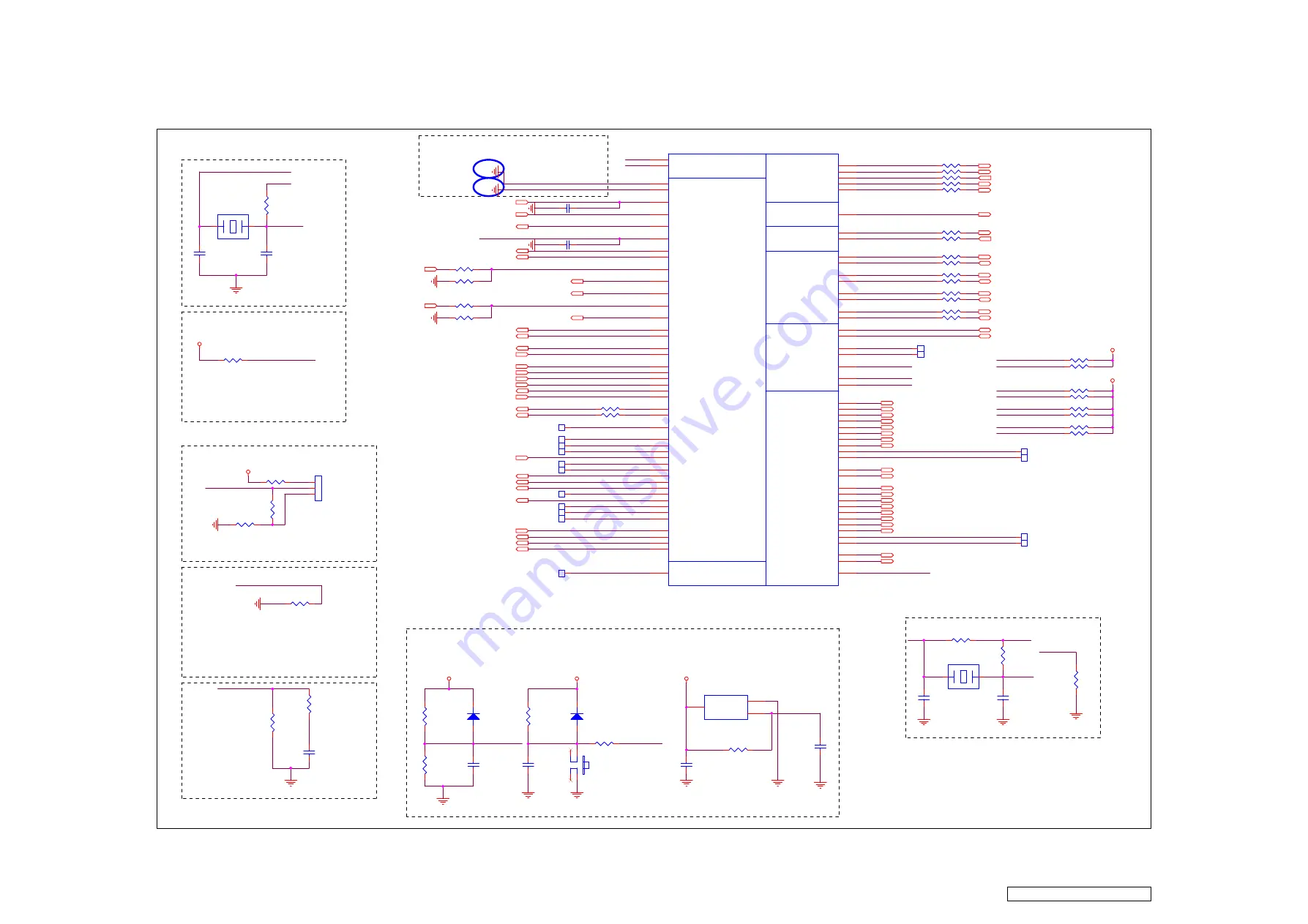
SIS328_MISC&OUTPUT

When the VIH of PS_ON is larger

than 3.3V, please stuff R376

and program PS_ON as open-dran

mode.

PS_ON

CLOCK OSC

Cload: 16pF

LVDS

HSGPIO23 IS HW TRAP, AND CAN
NOT BE USED AS OTHER
FUNCTION

AUX PWR:Red LED

Main PWR:Green LED

.

IC Vi

請留意 接地時請勿於

底下直接打

a

 IC 

需拉至

外在接地

Reset Function

Cload: 20pF

USB

H: enable booting menu

default:short 2-3

Vth=3.08V

8 mils

SIS_HDMIA_SDA_R
SIS_HDMIA_SCL_R

SIS_VGA_SDA_R
SIS_VGA_SCL_R

SIS_HDMIB_SCL_R

SIS_HDMIB_SDA_R

XOSCI

XOSCO_R

XOSCO

HSAGPIO23

SIS_PSON

SIS_MS_SDA_A

SIS_MS_SCL_A

SIS_LVDS_SWING_C

HSAGPIO31

USB_REXT

SIS_VGA_SCL_R

SIS_MS_SDA_A_R

SIS_HDMIB_SDA_R

SIS_HDMIA_SDA_R

SIS_HDMIA_SCL_R

HSAGPIO21

XOSCI

HSAGPIO27

HSAGPIO23

USB_CLKO

GPIO29

HSAGPIO25

SIS_AMP_EN

XOSCO

HSAGPIO20

STBY_SP_N

SIS_VGA_SDA_R

328_AMP_RST_N

HP_DET

AV_CVBSO

GPIO1

HSAGPIO28

SIS_LVDSA_TX4_DN

VGA_WAKE

UARTB_RX

SIS_LVDSA_TX4_DP

USB_CLKI

SIS_LVDSB_TX4_DP

SIS_MS_SCL_A_R

SIS_HDMIB_SCL_R

HSAGPIO22

SIS_LVDS_SWING

SIS_LVDSB_TX4_DN

GPIO7

UARTB_TX

HSAGPIO26

HSAGPIO24

GPIO28

GPIO5

ENTEST

UARTA_TX_R
UARTA_RX_R

MAIN_PWROK

AUX_PWROK

USB_CLKI

USB_REXT

USB_CLKO_R

ENDEBUG

AUX_PWROK

SIS_EXT_RST_N

GPIO17

USB_CLKO_R

USB_CLKO

HSAGPIO22

MAIN_PWROK

SIS_LVDS_SWING

KEYPAD_PWRKEY_SIS_N

14

SIS_LCDVDD_EN

15

FLASH_SPI_DI 14

SIS_SPI_DO 14

SIS_SPI_CLK 14

SIS_SPI_CS1_N 14

DEBUG0

14

SIS_HDMIB_SCL 11
SIS_HDMIB_SDA 11

SIS_HDMIA_SCL 11
SIS_HDMIA_SDA 11

SIS_VGA_SDA 12

SIS_VGA_SCL 12

SIS_LVDSA_TX2_DN 15
SIS_LVDSA_TX3_DP 15

SIS_LVDSA_TX0_DP 15

SIS_LVDSA_TX1_DP 15

SIS_LVDSA_TX0_DN 15

SIS_LVDSA_TX1_DN 15
SIS_LVDSA_TX2_DP 15

SIS_LVDSA_CLK_DP 15

SIS_LVDSB_TX0_DP 15

SIS_LVDSA_CLK_DN 15

SIS_LVDSB_TX1_DN 15

SIS_LVDSB_TX0_DN 15

SIS_LVDSA_TX3_DN 15

SIS_LVDSB_TX1_DP 15

SIS_LVDSB_TX2_DN 15

SIS_LVDSB_TX2_DP 15

PWM2

16

SIS_MS_SCL_A 18
SIS_MS_SDA_A 18

SIS_BL_EN

16

SIS_PSON

16

AUX_PWROK

14

SIS_R_LED

14

SIS_G_LED

14

DEBUG1

14

DEBUG2

14

DEBUG3

14

DEBUG5

14

DEBUG4

14

HP_DET

13

SIS_SPI_CS0_N 14

SIS_MUTE_SP_N

10

SIS_LVDSB_TX3_DN 15

SIS_LVDSB_TX3_DP 15

SIS_USBA_DN 14

SIS_USBA_DP 14

SIS_LVDSB_CLK_DP 15
SIS_LVDSB_CLK_DN 15

IR_SIS

14

UARTA_RX

12

UARTA_TX

12

UARTB_TX

14

UARTB_RX

14

VGA_EDID_WP

12

HEADPHONE/LINEOUT_MUTE

13

DATA_FLASH_WP_N

14

CODE_FLASH_WP_N

14

SIS_EXT_RST_N

18

MCU_INTR

14

MCU_SCLK

14

MCU_SDA

14

AUDIO_EN

19

AUDIO_DAC_EN

19

RS232_EN_VGA

12

VGA_HSYNC

5,12

VGA_VSYNC

5,12

V_5V_AUX

V_5V_AUX

GND

GND

V_3.3V

GND

GND

GND

GND

V_3.3V

GND

V_3.3V_AUX

GND

GND

GND

GND

GND

GND

V_3.3V_AUX

GND

GND

V_3.3V_AUX

GND

GND

GND

GND

R357

33R

C444

10uF_10V

TP101

R375

0R

CLOCK

MISC

IR

SPI

RS232

I2C

USB

LVDS

CVBS OUTPUT

I121A
sis328_ATSC_V02

AL24

AK24

AK25

AJ22

AM24

AM25

AL29

AK29

AM28

AH26

AM15

AL15

AK15

AH15

AJ15

AM16

AL16

AM17

AK16

AJ16
AL17

AK17

AM18

AH17

AL18

AJ18

AK18

AM19

AL19

AG19

AK19
AK20

AK22
AM23
AL23
AG21
AK23

AG25

AJ27
AK27

A20
B20

C19
D19

C18

B18
A18

AG23
AH22

AL25
AM26

F29
E29

F9

E9

B9

A9

D10

C10

E11
F11
A11
B11

C12
D12

E13
F13

A13
B13
C14
D14
E15
F15
A15
B15
C16
D16

A12

AM27
AL27

AF29

AH19

AM20

AL20

AM21

AL21

AK21

AJ21

AM22

AL22
AJ20

AH27

AK28

AJ28
AL28

AUX_PWROK

PWRBTN_N

PS_ON

ENTEST

ENDEBUG

MAIN_PWROK

OSCI
OSCO

PWM0
PWM1

HSAGPIO0 / VGA_WAKE

HSAGPIO1 / BL_EN

HSAGPIO2 / LCDVDD_EN

HSAGPIO3 / STBY_N_SP

HSAGPIO4 / MUTE_N_SP

HSAGPIO5 / BLK_LED0
HSAGPIO6 / BLK_LED1

HSAGPIO8 / HP_DET

HSAGPIO7 / HP_AMP_EN

HSAGPIO9 / DEBUG0
HSAGPIO10 / DEBUG1
HSAGPIO11 / DEBUG2
HSAGPIO12 / DEBUG3
HSAGPIO13 / DEBUG4
HSAGPIO14 / DEBUG5

HSAGPIO15 / VIDEO_SW0
HSAGPIO16 / VIDEO_SW1

HSAGPIO17/TUNER_ATV_PWR_EN

HSAGPIO18/AMP_RST_N
HSAGPIO19/AMP_EN
HSAGPIO20
HSAGPIO21

SPI_CLK

SPI_DO

SPI_DI

SPI_CS0_N
SPI_CS1_N

IR

UARTA_TX

UARTA_RX

USBA_P

USBA_N

USBB_P

USBB_N

USB_REXT

USB_CLKI

USB_CLKO

HDMIA_SCL

HDMIA_SDA

HDMIB_SCL

HDMIB_SDA

I2CMA_SCL

I2CMA_SDA

LVDSA_TX0N

LVDSA_TX0P

LVDSA_TX1N

LVDSA_TX1P

LVDSA_TX2N

LVDSA_TX2P

LVDSA_TX3P

LVDSA_TX3N

LVDSA_TX4P

LVDSA_TX4N

LVDSA_CLKP

LVDSA_CLKN

LVDSB_CLKP

LVDSB_CLKN

LVDSB_TX0P

LVDSB_TX0N

LVDSB_TX1P

LVDSB_TX1N

LVDSB_TX2P

LVDSB_TX2N

LVDSB_TX3P

LVDSB_TX3N

LVDSB_TX4P

LVDSB_TX4N

LVDS_EXTSWING

VGA_SCL

VGA_SDA

AV_CVBSO

HSAGPIO22
HSAGPIO23
HSAGPIO24
HSAGPIO25
HSAGPIO26
HSAGPIO27
HSAGPIO28
HSAGPIO29
HSAGPIO30
HSAGPIO31/CLK49M_OUT

HVAGPIO32/UARTBRX
HVAGPIO33/UARTBTX
HVAGPIO34/PWM2
HVAGPIO35/PWM3

R367

33R

X101
24.576MHz

1

2

TP212

C435

20pF

I124

APX809-31SA_SOT23

1

3

2

GND

VCC

RESET#

R390
NC/6.19K_1%

R380

0R

D128
1N4148

1

2

R101

0R

S101
BUTTON

1

3

2

4

TP227

R370

33R

R369

4.7K

X103

12MHz

1

2

TP225

C442
1uF_16V

TP224

R395
NC/22K

R393

3.3K

R381

0R

R354

2.2K

R376

NC/4.7K

TP214
TP215

TP222

R373

33R

C438
30pF

TP226

R396

3.3K

R385

NC/100K

R392
6.04K_1%

TP219

R389
0R

R360

NC/4.7K

R386
1K_1%

C436

20pF

R382

10K

JP06

1x3HEADER_SW

1
2
3

1
2
3

R372

33R

R384

10K

R403

1.8K

R387
10K

R366

33R

R368

4.7K

R363

33R

TP211

R352

2.2K

R359

33R

R404

1.8K

TP209

R355

33R

C434

NC/100nF_16V

R391

NC/10K

TP105

R365

33R

R358

33R

D127

1N4148

1

2

TP210

R374

0R

C437

NC/100n_16V

TP217

R364

47K

R361

47K

R356
33R

C440
NC/100nF_16V

C441

NC/100nF_16V

R371

33R

R383

10K

R353

33R

C439
30pF

R388
10K

TP220

C443
NC/47pF

TP216

R362

NC/4.7K

R394
NC/10K

8

. Schematic Diagrams 

ViewSonic Corporation


Confidential - Do Not Copy


N4285p-4M

61

Содержание N4285p-4M

Страница 1: ...Service Manual ViewSonic N4285p 4M Model No VS11983 4M 42 LCD TV N4285p 4M_SM Rev 1a Oct 2009 ViewSonic 381 Brea Canyon Road Walnut California 91789 USA 800 888 8583...

Страница 2: ...d specifically disclaims any warranty of merchantability or fitness for any particular purpose Further ViewSonic reserves the right to revise this publication and to make changes from time to time in...

Страница 3: ...rcuit Description 26 5 Adjustment Procedure 30 6 Trouble Shooting Flow Chart 57 7 Block Diagram 60 8 Schematic Diagrams 61 9 PCB Layout Diagrams 79 10 Exploded View And Exploded Parts List 81 11 Recom...

Страница 4: ...mmediately Long contact with water may cause discoloration or spots 4 When the panel surface is soiled wipe it with absorbent cotton or other soft cloth 5 Since the panel is made of glass it may break...

Страница 5: ...izer Surface of the LCD panel is pressed by fingers and that may cause Mura Take out the monitor with cushions Taking out the monitor by grasping the LCD panel That may cause Mura Place the monitor on...

Страница 6: ...king Sag or Smearing artifacts when driven by the specified video cards see 7 1 General Test Equipment in the primary mode VGA at 60 Hz and after user adjustment b No image drift or lose fine tune set...

Страница 7: ...pendix 3 Audio Audio amp of this product shall be provided by YAMAHA with a Model Number of YDA148 SiS SiS328MX for N4285p 4M shall be used as sound processor In addition a pair of speakers shall be i...

Страница 8: ...shall be defined in accordance with ISO 7779 DIN EN27779 1991 Power Switch noise shall be Excluded 12 Efficiency 80 full load nominal line 13 Leakage Current 0 5mA 240VAC 14 Power Saving DPMS 1 0 Wat...

Страница 9: ...n IR remote control unit shall accompany this product along with battery In addition this remote control unit shall have an operational distance of 5 meters and an operational angle of 15 degrees for...

Страница 10: ...nt 200mm x 400 mm VESA high hole n 4 pattren 6mm 1 0 pitch x 10 mm long screw mounting kit not included Sample Sample of textured color chips plastic material specification and Material Safety Data Sh...

Страница 11: ...p in amber when the TV is in standby mode 4 ENTER Display Input source selection menu enter a menu or enable the function while in OSD menu 5 CH Up Channel up when source is TV or select a control whi...

Страница 12: ...e RGB output of your computer and the other end to the RGB input on the rear of the LCD TV 7 YPbPr 2 signal input Connect this port to the YPbPr output of A V device 8 YPbPr 1 signal input Connect thi...

Страница 13: ...Connect this port to your A V device with audio in RCA connectors or to audio amplifier 16 Headphone Jack Connect to your headphones By connecting the headphones you can listen to the sound from the T...

Страница 14: ...Press this button to turn the power on from standby mode Press it again to return to the standby mode 2 MTS Press this button to choose the available sound output that is preset by TV broadcasting sta...

Страница 15: ...TV source 7 ZOOM Press this button repeatedly to select the screen size You can select from Normal Zoom 1 or Zoom 2 8 0 9 number buttons Press 0 9 and to select a channel After you input the channel n...

Страница 16: ...tween TV CATV or press to direct to TV source when in any other source 16 PICTURE Press this button to select between the picture modes of User Vivid Normal or Movie 17 WIDE Press this button to selec...

Страница 17: ...RETURN see Figure 1 3 Select Clock Mode from Auto or Manual then press ENTER to continue see Figure 2 4 Select Time Zone of your location then press ENTER to continue see Figure 3 5 Select TV RF sour...

Страница 18: ...ress 8 press 0 press press 3 Return to the previous channel press RETURN button Adjusting the Volume Press VOL to adjust volume To turn off the volume press MUTE To restore volume press MUTE again or...

Страница 19: ...button on the remote control 2 Press or to select the required input source between TV AV S Video YPbPr 1 YPbPr 2 HDMI 1 HDMI 2 VGA or USB When in USB input source the system only supports JPEG image...

Страница 20: ...the level 5 Press MENU to exit 2 1 Press the MENU button to display the OSD main menu 2 Press or to select your desired top Menu 3 Press ENTER or to enter the menu 4 Press or to select the control of...

Страница 21: ...me Zone select the Time Zone of your area with or Channel Skip Setting You can use the Channel Skip function to set some channels to be skipped the skipped channels will not appear on the screen when...

Страница 22: ...on then press ENTER or to enter Close Caption setting 3 Press or to select Analog CC or Digital CC and use or to select caption information To perform custom digital caption style settings select Digi...

Страница 23: ...t Change PIN then press ENTER to enter Change PIN setting 2 Enter your new password in Enter New PIN 3 Enter the new password again in Confirm New PIN After you complete the last step the screen will...

Страница 24: ...re defined as following E Exempt C children C8 children eight years and older G general programming suitable for all audiences PG parental guidance 14 viewers and older 18 adult programming 2 Press EN...

Страница 25: ...menu 2 Press or to select the Video menu 3 Press ENTER or to enter Video menu 4 Press or to select your desired controls and press or to adjust 4 For advanced VGA functions select VGA only enabled in...

Страница 26: ...only enabled in VGA source H Position To adjust the horizontal position of the picture V Position To adjust the vertical position of the picture Phase To adjust delay time of phase in order to reduce...

Страница 27: ...time Timer To set power on time Time Zone To select the time zone appropriate to your location Daylight Saving To turn on off daylight saving Close Caption To set close caption options CC mode To sel...

Страница 28: ...trol VOL VOL MENU MENU EXIT CH CH INPUT ENTER In USB mode the OSD function keys are as follows Thumbnail To display in thumbnail Slide Show Press this key to auto play the pictures Intervals can be ad...

Страница 29: ...z ADC the 170MHz triple video ADC and the HDMI 1 3 receiver respectively to minimize the deployment of the external components The audio ADC thus supports 5 Stereo Line in inputs The analog 54 MHz ADC...

Страница 30: ...it gain 7 bit offset adjustment Full Sync processing including SOG Automatic and programmable power saving modes 1 4 Dual Channel DVI HDCP HDMI Compliant Receiver Support up to 225MHz 1080P 60Hz with...

Страница 31: ...h Compressed Audio MPEG AC 3 and AAC or Stereo PCM Outputs Support up to7 1 channel I2S outputs HDMI audio processing capability Automatic compensation of processing skew between Video and Audio path...

Страница 32: ...t Dual UART 1 16 Process and Package Type 0 11um 3 3V 1 2V process 708 pin TEBGA package 4 2 GPIO Interface The GPIO signals in SiS 328 are all multi function pins The default function is designated i...

Страница 33: ...des Pattern 1 4 1 EEPROM INIT A Press POWER CH and ENTER at the same time then go into the FACTORY MODE Fig 1 B Figure 1 Select EEPROM INITIAL and press ENTER The act of EEPROM INITIAL is completed wh...

Страница 34: ...TEST A Input YPbPr S VIDEO AV signal and check B Under YPbPr MODE Make sure the 480i 480P 720P 1080i 1080p is right 1 4 9 AUDIO FUNCTION TEST A Audio input includes PC AUDIO IN S VIDEO AV AUDIO IN an...

Страница 35: ...589 75 595 75 601 75 607 75 613 75 619 75 625 75 631 75 637 75 643 75 101 00 107 00 113 00 123 00 129 00 221 00 227 00 233 00 239 00 245 00 251 00 257 00 517 00 523 00 529 00 535 00 541 00 547 00 553...

Страница 36: ...00 263 00 269 00 275 00 281 00 287 00 293 00 299 00 305 00 311 00 317 00 323 00 329 00 335 00 341 00 347 00 353 00 359 00 365 00 371 00 377 00 383 00 389 00 395 00 JJ KK LL MM NN OO PP QQ RR SS TT UU...

Страница 37: ...er LEVEL 60dBu regards as normally PRODUCTS OUTPUT CHECK ITEM A The same as CENTRALISM TRANSMITTING SIGNAL CHECK CONTENT B saturation TEST inputs the TV signal the input signal LEVEL establishment mos...

Страница 38: ...0 080ms 0 106ms V Border 0 000ms 0 254ms 0 000ms 0 000ms H V Sync Interlace No No No No ITEM 5 6 7 8 TIMING 800 600 75HZ 1024 768 60HZ 1024 768 75HZ 1280 768 60HZ Pixel Rate 49 500MHZ 65 000MHZ 78 75...

Страница 39: ...11 487us 13 863us H B Porch 2 994us 2 296us 1 915us 0 578us H Width 1 310us 1 037us 1 203us 0 231us H Border 0 000us 0 000us 0 000us 0 000us V TOTAL 16 662ms 16 661ms 16 679ms 16 686ms V DISPLAY 16 09...

Страница 40: ...onform to the LCD TV you have to do the DDC key in 2 1 Equipment Needed N4285P4M LCD TV DDC Card PC RS 232 cable Barcode Reader VGA Cable N4285P4M LCD TV DDC Card PC RS 232 Cable VGA Cable Barcode Rea...

Страница 41: ...able when key in DVI DDC information use VGA transform to DVI port 2 2 4 Connect Power Cord to N4285P4M LCD TV 2 2 5 Press MENU and ENTER at the same time then go into the BURN IN MODE 2 3 DDC Key In...

Страница 42: ...2 3 3 Press ENTER key 2 3 4 Press F4 key and Input bar code ViewSonic Corporation Confidential Do Not Copy N4285p 4M 39...

Страница 43: ...2 3 5 Press ENTER key then the successful picture is as follows DDC DOWNLOAD OK 2 3 6 Exit program ViewSonic Corporation Confidential Do Not Copy N4285p 4M 40...

Страница 44: ...he different EDID into each HDMI connector 3 1 Equipment Needed N4285P4M LCD TV PC RS 232 cable Barcode Reader HDMI Cable N4285P4M LCD TV PC RS 232 Cable HDMI Cable Barcode Reader 3 2 Setup Procedure...

Страница 45: ...keyboard port 3 2 3 Connect DDC Card and N4285P4M LCD TV with HDMI Cable 3 2 4 Connect Power Cord to N4285P4M LCD TV 3 3 DDC Key In Procedure 3 3 1 Run DDC exe 3 3 2 Choose model number then ViewSonic...

Страница 46: ...3 3 3 Press ENTER key 3 3 4 Press F4 key ViewSonic Corporation Confidential Do Not Copy N4285p 4M 43...

Страница 47: ...3 3 5 Input bar code 3 3 6 Press ENTER key then the successful picture is as follows DDC DOWNLOAD OK 3 3 7 Exit program ViewSonic Corporation Confidential Do Not Copy N4285p 4M 44...

Страница 48: ...es of codeFlash code custom save and dataFlash data into the folder of N4285p 4M 4 2 3 Insert the USB sticker into the TV 4 2 4 Select the TV source 4 2 5 Enter Factory Mode Method 1 Press the MENU ke...

Страница 49: ...d seal the bag Figure 2 1 3 Put the cushions on the LCD TV and put all the accessories into the carton Figure 3 1 4 Place the LCD TV into the carton At last close the carton and seal it with tape Figu...

Страница 50: ...2013222536P POLYETHY BAG 1 7 NA 2438501329P CD OWNER GUIDE 1 8 NA 2002310761P GUARANT CARD 1 9 A 00005362 2427130046P AC POWER CORD 1 10 NA 2011100017P CARTON BOX 1 11 P 00009779 2011142139P CARTON BO...

Страница 51: ...om LCD TV 1 1 Unscrew 4 screws that secure Stand Unit and detach Dust Cover from the LCD TV 2 Disassembly of Rear Cover 2 1 Pull the Holder from the LCD TV 2 2 Unscrew 23 screws in the Rear Cover Stan...

Страница 52: ...2 3 Prize the rectangle hole on Rear Cover Fig 1 with a screwdriver Fig 2 to make the Rear Cover detach from the LCD TV Fig 1 Fig 2 ViewSonic Corporation Confidential Do Not Copy N4285p 4M 49...

Страница 53: ...3 Disassembly of Main Board Power Board IR Board Front Cover and Panel Unit 3 1 Unscrew 24 screws to remove Shield Plate Rear Cover ViewSonic Corporation Confidential Do Not Copy N4285p 4M 50...

Страница 54: ...3 2 Remove the function key ass y 3 3 Unscrew 18 screws to remove Front Cover and Bracket Fix ViewSonic Corporation Confidential Do Not Copy N4285p 4M 51...

Страница 55: ...3 4 Unscrew 17 screws to remove metal fiting vesa support Bracket Fix ViewSonic Corporation Confidential Do Not Copy N4285p 4M 52...

Страница 56: ...4 Unscrew 17 screws and to remove Shield plate 3 5 Unscrew 6 screws and disconnect the wires to remove Power Board Power Board Shield plate ViewSonic Corporation Confidential Do Not Copy N4285p 4M 53...

Страница 57: ...3 6 Unscrew 5 screws and disconnect the wires to remove Main Board 3 7 Unscrew 5 screws to remove METAL FITTG I O Main Board METAL FITTG I O ViewSonic Corporation Confidential Do Not Copy N4285p 4M 54...

Страница 58: ...3 8 Lay Panel Unit facedown and unscrew 18 screws on its right left up and down sides to remove Panel Unit and Panel Bracket ViewSonic Corporation Confidential Do Not Copy N4285p 4M 55...

Страница 59: ...Panel Unit ViewSonic Corporation Confidential Do Not Copy N4285p 4M 56...

Страница 60: ...is on C183 Check IR Board Check X101 is OK Check Wire Connection on power module is OK Replace I121 Replace I113 Replace IR board Replace X101 Connect the wire Replace Power module NO NO NO NO NO YES...

Страница 61: ...CE TV Check I103 Pin14 has output signal Check I121 signal output to I601 Check Speaker Wire Replace I103 Replace I121 AV S VIDEO YPbPr YES YES NO NO ViewSonic Corporation Confidential Do Not Copy N42...

Страница 62: ...I105 DTV Check I102 has output signal at RP01 RP02 Check clock output YES NO Replace I102 NO Replace X101 NO YES Check P117 P118 I600 is defective Replace P117 P118 HDMI Check I121 has output signal a...

Страница 63: ...AUDIO INPUT HDMI1 YPP2 YPP1 USBA BUS VGA CONN VIDEO INPUT YPP1 PORT1 YPP2 PORT2 RCA2 2 CONN SIS328 DIF AV1 SV CONN VIDEO INPUT AV1 SV ATSC TUNER DTVS205EH201A DRAM AUDIO INPUT AV1 SV1 AUDIO OUTPUT LVD...

Страница 64: ...GND GND GND R357 33R C444 10uF_10V TP101 R375 0R CLOCK MISC IR SPI RS232 I2C USB LVDS CVBS OUTPUT I121A sis328_ATSC_V02 AL24 AK24 AK25 AJ22 AM24 AM25 AL29 AK29 AM28 AH26 AM15 AL15 AK15 AH15 AJ15 AM16...

Страница 65: ...C420 100nF_16V C421 47nF_16V C391 220nF_16V C0603 R336 37 4_1 C411 47nF_16V R335 37 4_1 R337 37 4_1 C395 47nF_16V C389 47nF_16V C412 220nF_16V C0603 R408 33R C432 100nF_16V C429 NC 22pF C430 100nF_16...

Страница 66: ...R314 NC 47K R412 100K R302 NC 47K C379 1uF_16V C355 10uF_10V C383 NC 1nF R310 0R 1K C380 NC 1nF R321 NC 47K C365 100nF_16V C376 1uF_16V R413 100K R311 47K C387 NC 330pF R320 0R 1K R289 47K C374 NC 1n...

Страница 67: ...1 L2 K1 J1 J2 K3 AE5 AK3 AL4 AH5 AM5 AG6 AL5 AH6 AK6 AL6 AL7 AJ7 AM7 AK8 AM8 AL8 R2 R1 AJ4 AH4 T1 T2 U4 T3 U5 V5 AB3 W4 AB1 AA2 AA1 W5 Y3 Y1 W3 V4 W2 W1 V2 V1 U3 AJ2 AG3 AC4 AJ3 AD4 AB5 AC1 AA3 AC2 AC...

Страница 68: ..._MPLL AVSS1P2_MPLL AVDD1P2_USBCLK AVSS1P2_USBCLK AVDD1P2_LPLL AVSS1P2_LPLL AVDD3P3_XTAL_AUX AVSS3P3_XTAL_AUX AVDD3P3_LVDS AVDD1P2_HDMI AVDD1P2_HDMI AVDD3P3_HSADC AVDD3P3_HSADC AVDD3P3_HSADC1 AVDD3P3_H...

Страница 69: ...13 W14 W15 W16 W18 W19 W20 W21 Y12 Y13 Y14 Y15 Y16 Y17 V11 W11 Y11 Y22 V9 W9 Y2 Y4 Y9 W17 AG5 AJ17 AK4 B8 Y18 Y19 Y20 Y21 W22 J3 AG26 AH20 L12 L13 D29 D30 OVDD1P8_DDR PVDD3P3_DDR OVDD3P3 IVDD1P2_AUX V...

Страница 70: ...uF_63V DIP C623 220nF_50V 0805 R624 100R C622 100nF_50V 0603 R621 1K L606 15UH CHOKE 5mm C626 220nF_50V 0805 R626 NC 10K C614 NC 1nF C645 1uF_16V L608 15UH CHOKE 5mm R625 100R R696 1 5K R630 NC 0R C61...

Страница 71: ...CL 4 HDMIA_RX_CLK_DP 5 HDMIA_RX_CLK_DN 5 GND GND GND GND GND GND GND GND GND GND GND GND GND GND D153 4 7P R261 100R D151 4 7P D149 4 7P D158 4 7P D156 4 7P R260 NC 1K R195 100R R257 33R HDMI 19 P117...

Страница 72: ...pF R252 75R_1 R262 2K C415 390pF R457 75R_1 C392 390pF L144 80Z 1 2 D174 4 7P L150 80Z 1 2 R250 75R_1 C237 NC 33pF C409 22pF R248 75R_1 C242 NC 33pF L143 80Z 1 2 R401 100R C416 390pF R334 75R_1 D167 4...

Страница 73: ...GND V_3 3V GND GND GND GND GND GND GND GND GND GND GND GND GND GND L123 600Z 1 2 C225 1uF_16V L129 600Z 1 2 L138 600Z 1 2 D121 4 7P D118 4 7P D109 NC 4 7P C230 NC 1nF D110 4 7P R241 47K L122 600Z 1 2...

Страница 74: ...V_5V_AUX GND V_3 3V_AUX V_3 3V_SPI GND V_3 3V_SPI GND GND GND V_3 3V_SPI V_3 3V_SPI GND V_3 3V_AUX GND V_3 3V_AUX GND GND V_3 3V_AUX GND V_3 3V_AUX GND GND GND R473 4 7K R199 1 5K P109 B9B PH 1 2 3 4...

Страница 75: ...GNDPADL39X118 R184 NC 0R M1 HOLE GND GND32PDX 2 3 4 5 9 8 7 6 1 2 3 4 5 9 8 7 6 1 R191 0R L114 120Z0805_6 0A 1 2 R194 0R M7 HOLE GND GND32PDX 2 3 4 5 9 8 7 6 1 2 3 4 5 9 8 7 6 1 R178 NC 10K R181 47K R...

Страница 76: ...C0805 R162 330K B E C Q102 NC MMBT3904 C175 100nF_16V R165 0R 1K_1 I112 TPS54331 1 2 3 4 5 6 7 8 BOOT VIN EN SS VSNS COMP GND PH R425 2 2K C182 100nF_16V R422 NC C184 220uF_16V_LESR C181 220uF_16V_LE...

Страница 77: ...0nF_16V 1 2 R153 11K5_1 L110 120Z0805_3A 1 2 C160 100nF_16V C166 100uF_16V_LESR R453 NC 33K R455 NC 56K C457 NC 100nF_16V C169 100nF_50V 0603 R452 NC 2 21K_1 L451 NC 10uH YC124RT L107 120Z0805_3A 1 2...

Страница 78: ...6V_LESR I103 DTVS205EH201A 17 18 1 2 3 4 5 6 7 8 9 10 11 12 13 14 19 20 21 22 15 16 23 GND GND RF_AGC_TP NC VT 30V IF IF IF_AGC TUNER_IF_TP SCL SDA GND BP 5V NC AFT SIF GND GND GND GND CVBS GND GND C1...

Страница 79: ...06 1K C608 10uF_10V C610 10uF_10V R601 33R C604 4 7nF R602 33R R605 1K C602 100nF_16V R622 NC R612 5 6K R603 33R C605 4 7nF TP601 R613 5 6K R604 33R L601 80Z_0603 1 2 R615 10K R616 0R I602 PCM1754DBQR...

Страница 80: ...P F Center Frequecy 38Khz KEY1_ENTER KEY2_UP KEY5_DEC KEY0_MENU KEY3_DOWN KEY4_INC IR_IN 5VD LED_R LED_G PWRON GND K GND IR GND K GND IR GND IR GND IR S703 S701 D711 P712 JST 2 P 2 0 180 1 2 S704 P701...

Страница 81: ...23 34 EA VP X1 X2 RESET P3 2 INT0 P3 3 INT1 P3 4 T0 P3 5 T1 P1 0 T2 T1 1 T2EX P1 2 P1 3 P1 4 P1 5 P1 6 P1 7 P0 0 P0 1 P0 2 P0 3 P0 4 P0 5 P0 6 P0 7 P2 0 P2 1 P2 2 P2 3 P2 4 P2 5 P2 6 P2 7 P3 7 RD P3...

Страница 82: ...9 PCB Layout Diagrams 9 1 MAIN PCB TOP VIEW ViewSonic Corporation Confidential Do Not Copy N4285p 4M 79...

Страница 83: ...9 2 MAIN PCB BOTTOM VIEW ViewSonic Corporation Confidential Do Not Copy N4285p 4M 80...

Страница 84: ...9 3 CON PCB TOP VIEW 9 4 CON PCB BOTTOM VIEW ViewSonic Corporation Confidential Do Not Copy N4285p 4M 81...

Страница 85: ...9 5 IR PCB TOP VIEW 9 6 IR PCB BOTTOM VIEW ViewSonic Corporation Confidential Do Not Copy N4285p 4M 82...

Страница 86: ...9 7 SWITCH PCB TOP VIEW ViewSonic Corporation Confidential Do Not Copy N4285p 4M 83...

Страница 87: ...9 8 SWITCH PCB BOTTOM VIEW ViewSonic Corporation Confidential Do Not Copy N4285p 4M 84...

Страница 88: ...9 9 RS232 PCB TOP VIEW ViewSonic Corporation Confidential Do Not Copy N4285p 4M 85...

Страница 89: ...9 10 RS232 PCB BOTTOM VIEW ViewSonic Corporation Confidential Do Not Copy N4285p 4M 86...

Страница 90: ...10 Exploded View And Exploded Parts List ViewSonic Corporation Confidential Do Not Copy N4285p 4M 87...

Страница 91: ...ViewSonic Corporation Confidential Do Not Copy N4285p 4M 88...

Страница 92: ...C429FE ABS94HB BLACK STANDARD 1 28 NA 2044266601P FUNCTION KEY JC278 ABS 94V0 AL PLATE FUNCTI 1 29 NA 2084730062P SCREW BND T M3X6 BND T 2 30 NA 2080003700P SCREW SPE ISZZTER001A M3 6L MSWR17 FZMYI 6...

Страница 93: ...8 2427411001P P711 20 Documentation Quick Start Guide CD Rom Label User s Guide CD ROM N4285P 4M WIZARD VS11983 4M CMO DC 00009842 2604208587 26042 21 Electronic Components CRT EEPROM Fly Back Transfo...

Страница 94: ...T TDK 1 49 NA 2345710496P 03 CAP CHIP CS 0402 Y5V 16V 0 1u Z T WALSIN 1 50 NA 2345710496P 01 CAP CHIP CS 0402 Y5V 16V 0 1u Z T DARFON 1 51 NA 2345710496P 02 CAP CHIP CS 0402 Y5V 16V 0 1u Z T TDK 1 52...

Страница 95: ...5V 10V 10u Z T WALSIN 1 144 NA 2345710496P 01 CAP CHIP CS 0402 Y5V 16V 0 1u Z T DARFON 1 145 NA 2345710496P 02 CAP CHIP CS 0402 Y5V 16V 0 1u Z T TDK 1 146 NA 2345710496P 03 CAP CHIP CS 0402 Y5V 16V 0...

Страница 96: ...A 2340133096P CAP CHIP CS 0402 NPO 50V 33p J T 1 244 NA 2345710496P 01 CAP CHIP CS 0402 Y5V 16V 0 1u Z T DARFON 1 245 NA 2345710496P 02 CAP CHIP CS 0402 Y5V 16V 0 1u Z T TDK 1 246 NA 2345710496P 03 CA...

Страница 97: ...CAP CHIP CS 0402 X7R 16V 0 047u K T 1 343 NA 2345347396P CAP CHIP CS 0402 X7R 16V 0 047u K T 1 344 NA 2345347396P CAP CHIP CS 0402 X7R 16V 0 047u K T 1 345 NA 2345710496P 01 CAP CHIP CS 0402 Y5V 16V 0...

Страница 98: ...7R 16V 1 0u K T WALSIN 1 440 NA 2340122196P CAP CHIP CS 0402 NPO 50V 220p J T 1 441 NA 2347122496P 01 CAP CHIP CS 0805 X7R 50V 0 22u K T DARFON 1 442 NA 2347122496P 02 CAP CHIP CS 0805 X7R 50V 0 22u K...

Страница 99: ...0P M 1 539 NA 2436247996P VARISTOR ESD V PORT 0603 4 7P M 1 540 NA 2436250996P VARISTOR ESD V PORT 0603 5 0P M 1 541 NA 2436247996P VARISTOR ESD V PORT 0603 4 7P M 1 542 NA 2436250996P VARISTOR ESD V...

Страница 100: ...360106T BEAD HI IMPEDANCE Z 600 ohm 200MHZ 0603 200mA 1 641 NA 2379360106T BEAD HI IMPEDANCE Z 600 ohm 200MHZ 0603 200mA 1 642 NA 2379360106T BEAD HI IMPEDANCE Z 600 ohm 200MHZ 0603 200mA 1 643 NA 237...

Страница 101: ...T 1 738 NA 2251166506P RES CHIP 1 16W RC 0402 1 16W 665 ohm F T 1 739 NA 2251166506P RES CHIP 1 16W RC 0402 1 16W 665 ohm F T 1 740 NA 2251180606P RES CHIP 1 16W RC 0402 1 16W 806 ohm F T 1 741 NA 22...

Страница 102: ...F T 1 837 NA 2253110296P RES CHIP 1 16W RC 0402 1 16W 1K ohm J T 1 838 NA 2253110296P RES CHIP 1 16W RC 0402 1 16W 1K ohm J T 1 839 NA 2253122296P RES CHIP 1 16W RC 0402 1 16W 2 2Kohm J T 1 840 NA 225...

Страница 103: ...B FR4 4 320 170mm V1 00 09 11 2009 1 939 NA 2072263001P HEAT SINK AL 23 5 23 5 8T 3M 467MP 200MP 1 940 NA 27201C11300 V TYPE MAIN N4285P 4M 1 941 NA 2336010543P HI LIFE LOW ESR E CAP 3000hr EC 1u 50V...

Страница 104: ...WALSIN 1 1035 NA 2345710496P 01 CAP CHIP CS 0402 Y5V 16V 0 1u Z T DARFON 1 1036 NA 2345710496P 02 CAP CHIP CS 0402 Y5V 16V 0 1u Z T TDK 1 1037 NA 2345710496P 03 CAP CHIP CS 0402 Y5V 16V 0 1u Z T WALSI...

Страница 105: ...1u Z T TDK 1 1134 NA 2345710496P 03 CAP CHIP CS 0402 Y5V 16V 0 1u Z T WALSIN 1 1135 NA 2345710496P 01 CAP CHIP CS 0402 Y5V 16V 0 1u Z T DARFON 1 1136 NA 2345710496P 02 CAP CHIP CS 0402 Y5V 16V 0 1u Z...

Страница 106: ...0402 1 16W 0 ohm J T 1 1232 NA 2253100096P RES CHIP 1 16W RC 0402 1 16W 0 ohm J T 1 1233 NA 2253100096P RES CHIP 1 16W RC 0402 1 16W 0 ohm J T 1 1234 NA 2253100096P RES CHIP 1 16W RC 0402 1 16W 0 ohm...

Страница 107: ...SMD PMBS3904 SOT 23 PHILIPS 1 1333 NA 2253210596P RES CHIP 1 10W RC 0603 1 10W 1 0Mohm J T 1 1334 NA 2253247296P RES CHIP 1 10W RC 0603 1 10W 4 7Kohm J T 1 1335 NA 2253210396P RES CHIP 1 10W RC 0603 1...

Страница 108: ...AE 65UA RSS232 ABS94HB BLACK 1 1427 NA 2074163400P HOLDER JC429FE CABLE CLIP P P BLACK 1 1428 NA 2055636114P LABEL N4285P 4M VS11983 4M SMALL LABEL 1 1429 NA 2055617101P LABEL 10 20 HI POT TESTED OK 1...

Страница 109: ...escription 5 Adjusting Procedure 6 Trouble Shooting Flow Chart 7 Block Diagram 8 Schematic Diagrams 9 PCB Layout Diagrams 10 Exploded View And Exploded Parts List 11 Recommended Spare Parts List B Are...

Отзывы: