background image

Installation on a Wall

38

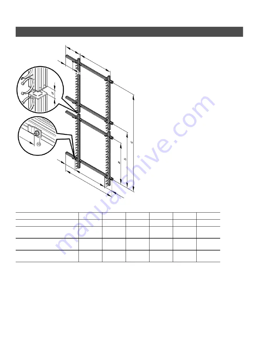
Installing the Mounting Rails

Center the mounting rails, maintaining
dimension d=1” / 26mm

Number of collectors

1

1

2

2

2

2

Number of tubes

20

30

20/20

20/30

30/20

30/30

a

mm
inches

850

33.5

1260

49.6

850

33.5

850

33.5

1260

49.6

1260

49.6

b

mm
inches

––
––

––
––

1465

57.7

1615

63.6

2025

79.7

2175

85.6

c

mm
inches

––
––

––
––

2315

91.1

2875

113.2

2875

113.2

3435

135.2

d

1” / 26mm

e

16.9” / 430mm

f

61.4” / 1560mm

g

7.9” / 200mm

h

9.1” / 230mm

i

65.0” / 1650mm

j

7.9” /200mm

k

80.7” / 2050mm

Note:

See page 37 for numbered parts
description.

5

3

6

8

5

3

8

v

1

.1

g

f

h

e

i

j

k

Содержание VITOSOL 200-T SD2A 2m2 Series

Страница 1: ...uctions Vitosol 200 T Model SD2A 2m2 Series Model SD2A 3m2 Series Vacuum tube solar collector utilizing the direct flow principle to harness solar energy VITOSOL 200 T 5368 538 v1 1 11 2010 Please file in Service Binder ...

Страница 2: ...tning protection of the solar system In the lower part of the building install an electrical conductor on the piping system of the solar circuit in compliance with local regulations Connection of the solar system to a new or existing lightning protection or the provision of local grounding should only be carried out by a licensed professional who must take into account the prevailing conditions on...

Страница 3: ...mponents 9 Installation on Shingled Roof 10 Installing the Mounting Rails 13 Installing the Connection Housing 15 Installation on Sloped Roofs Vertical Tube Orientation Overview of System Installation 16 Overview of System Components 17 Installation on Shingled Roof 18 Installing the Mounting Rails 21 Installing the Connection Housing 23 Installation on Flat Roofs Overview of System Installation 2...

Страница 4: ...allation 36 Overview of System Components 37 Installing the Mounting Rails 38 Installing the Connection Housing 41 Hydronic Connections Joining the Connection Housings 42 Installing the General Connection Kit and Collector Temperature Sensor 43 Installing the Vacuum Tubes 45 Removing the Vacuum Tubes if required 46 Collector Supply and Return Piping 47 Sample System Layout 47 Appendix System Insta...

Страница 5: ...nd maintenance of hot water heating systems There are no user serviceable parts on this equipment Ensure main power supply to equipment the heating system and all external controls has been deactivated Close main oil or gas supply valve Take precautions in both instances to avoid accidental activation of power during service work The completeness and functionality of field supplied electrical cont...

Страница 6: ...icates that other instructions must be referenced Product Information Please refer to the Vitosol 200 T Technical Data Manual for complete technical information and product description The Technical Data Manuals are available for download at www viessmann ca or www viessmann us com Vitosol 200 T Model SD2A 2m2 Series Vacuum tube collector utilizing the direct flow principle with 20 tubes 22 ft 2 2...

Страница 7: ...utside the building should be insulated to avoid heat loss Use only high temperature resistant pipe insulation Collector Location Please refer to the Vitosol System Design Guidelines for detailed information on the optimum alignment and inclination of solar collectors Optimum alignment and inclination The solar collector provides the highest solar yield over an annual average when facing south wit...

Страница 8: ...for sloped roofs Panels can be stacked one above the other or side by side Note Refer to page 43 for supply and return piping configurations For this installation method the general connection set with air vented u pipe must be used The collectors must be installed so that the vacuum tubes are slightly inclined upwards towards the header A slope of 1 4 per ft is recommended to eliminate air from b...

Страница 9: ...n housing Rubber retainer Vacuum tube Hydronic connection accessories Interconnection pipes 7188 620 General Connection Set 7268 267 consists of Retaining clip Connecting pipe short Connecting pipe long Profile clamp Compression fitting elbow Ø 22mm 90 Support sleeve U pipe U pipe with air vent with 7268 268 Insulation cap Screw Sensor Wall Set 7188 622 consists of wZ Brass compression tee Ø 22 mm...

Страница 10: ... 1 1 2 2 2 2 Number of tubes 20 30 20 20 20 30 30 20 30 30 a mm inches 1439 56 7 2149 35 6 1439 56 7 1439 56 7 2149 85 6 2149 85 6 b mm inches 1439 56 7 2149 85 6 1439 56 7 2149 85 6 c mm inches 850 33 5 1260 49 6 850 33 5 850 33 5 1260 49 6 1260 49 6 d mm inches 1465 57 7 1615 103 5 2025 79 1 2175 85 6 e mm inches 2315 91 1 2875 32 3 2875 113 2 3435 135 2 Note See page 9 for numbered parts descri...

Страница 11: ...ation on Sloped Roofs Horizontal Tube Orientation 11 Installation on Shingled Roof continued Note See page 9 for numbered part description 5368 538 v1 1 Center the mounting rails maintaining dimension f 1 26mm ...

Страница 12: ...ealant 5 Attach bracket to roof joist using appropriate stainless steel lag bolts or screws field supplied Lag bolt should penetrate the roof joist at least 2 64mm 6 Re apply shingles if required and ensure all roof penetrations are thoroughly sealed with silicone sealant 7 Continue with mounting rail installation on following page 5368 538 v1 1 Correct Incorrect Source CANSIA Source CANSIA Lag bo...

Страница 13: ... and nuts Ensure rail is aligned vertically and horizontally Ensure the mounting rail is installed with the single slot in the rail facing upwards 2 Align and secure the retaining plates onto the mounting rail 3 Secure mounting brackets onto the mounting rails 4 Align the mounting rails with tube holders and secure to the mounting brackets 5 Secure a mounting bracket onto the mounting rail on the ...

Страница 14: ...page 9 for numbered parts description 6 Secure the locking plate at the bottom of the mounting rails with tube holders to prevent tube rails from shifting 7 If a second collector is installed above the first insert a spacer bracket Proceed as per steps 2 to 5 for the second collector 5368 538 v1 1 7 6 90º 90º ...

Страница 15: ...ation rails must be in alignment with those in the connection housing align with string if necessary 3 Mark the fixing points at the back of the connection housing Use the centering groove as a template 4 Drill holes Ø 3 8 9mm 5 Secure the connection housing to the mounting rail 6 If several collectors are to be mounted one above the another go to subsection entitled Joining the Connection Housing...

Страница 16: ...eriods of stagnation are expected Horizontal tube orientation is recommended for applications that combine DHW and space heating supplement see page 8 If this installation method is used for applications that combine DHW and space heating supplement a heat rejection circuit must be used to avoid collector stagnation The collectors should be installed so that the header is slightly inclined upwards...

Страница 17: ...with tube holders Connection housing Rubber retainer Vacuum tube Hydronic connection accessories Interconnection pipes 7188 620 General Connection Set 7268 267 consists of Retaining clip Connecting pipe short Connecting pipe long Profile clamp Compression connector elbow Support sleeve U pipe U pipe with air vent with 7268 268 only Insulation cap Screw Sensor Wall Set 7188 622 consists of Brass co...

Страница 18: ...al Tube Orientation 18 Installation on Shingled Roof 61 4 1560mm 65 1650mm 17 430mm 9 230mm Collector Mounting rail Roof bracket Roof sheathing complete with shingles Collector installation rail with tube holders Lag bolts 5368 538 v1 1 ...

Страница 19: ...0 49 6 850 33 5 850 33 5 1260 49 6 b mm inches 1465 57 7 1820 71 7 2175 85 6 c mm inches 850 33 5 1260 49 6 1260 49 6 d mm inches 2315 91 1 2875 113 2 3435 135 2 e mm inches 615 24 2 765 30 1 915 36 0 f 1 26mm g 61 4 1560mm h 17 430mm i 65 1650mm Note Please see page 17 for numbered part description 5368 538 v1 1 Center the mounting rails maintain dimension f 1 26mm i h g a 2 c 2 7 4 187 5mm ...

Страница 20: ...alant 5 Attach bracket to roof joist using appropriate stainless steel lag bolts or screws field supplied Lag bolt should penetrate the roof joist at least 2 64 mm 6 Re apply shingles if required and ensure all roof penetrations are thoroughly sealed with silicone sealant 7 Continue with mounting rail installation on following page 5368 538 v1 1 Correct Incorrect Source CANSIA Source CANSIA Lag bo...

Страница 21: ...ween the installation rails is 1 26mm see page 19 Roof brackets 1 Secure the mounting rail to the roof brackets using T bolts washers and nuts Ensure rail is aligned vertically and horizontally Note Please see page 17 for numbered parts description 2 Align and attach the retaining plates onto the mounting rail 5368 538 v1 1 1 7 4 187 5 mm 2 9 1 230 mm ...

Страница 22: ...ing dimension f 1 26mm Note Please see page 17 for numbered parts description 3 Fit clamping brackets onto the mounting rails do not yet tighten the bolts 4 Click the mounting rails with tube holders into the clamping brackets align and fasten Note Tube holders on both rails must be aligned 5368 538 v1 1 3 4x 4 61 4 1560mm 17 430mm ...

Страница 23: ...ates 2 Align the connection housing The tube holders on the installation rails must be in alignment with those in the connection housing align with string if necessary 3 Tighten the mounting rails with the clamping brackets 4 If several collectors are to be mounted adjacently go to subsection entitled Joining the Connection Housings on page 42 otherwise go to subsection Installing the General Conn...

Страница 24: ...d to substructural frames Installations on flat roofs must have tubes installed to allow for proper venting of air The collector must be installed with an upward slope to the connection housing to allow air to escape A slope of 2 or 1 4 per foot is recommended Align the collector panel with the absorbers facing south and with the tubes mounted in an east west direction Maximum tube rotation is 25 ...

Страница 25: ...awl plug S10 Washer Hexagon screw 8 x 70mm Clamping bracket T slot bolt Washer Hexagon nut Mounting rail Mounting rail with tube holders Retaining plate Connection housing Vacuum tube Rubber retainer Note Refer to page 9 for the overview of all hydronic connection accessories 5368 538 v1 1 ...

Страница 26: ... ground level m ft 8 26 8 20 26 66 20 100 66 328 Model SD2A 2m2 3m2 2m2 3m2 2m2 3m2 Ballast A lb piece kg piece 48 4 22 72 6 33 96 8 44 143 0 65 145 2 66 215 6 98 Ballast B lb piece kg piece 57 2 26 85 8 39 101 2 46 151 8 69 147 4 67 222 2 101 1 Securing against slipping requires no additional attachment to roof Ballast weights required to secure against lifting 2 Installation height above ground ...

Страница 27: ...ast Weight A Ballast Weight B Number of collectors 1 1 2 2 2 2 Number of tubes 20 30 20 20 20 30 30 20 30 30 a mm inches 850 33 5 1260 49 6 850 33 5 850 33 5 1260 49 6 1260 49 6 b mm inches 1465 57 7 1615 63 6 2025 79 7 2175 85 6 c mm inches 2315 91 1 2875 113 2 2875 113 2 3435 135 2 d 1 26mm e 9 1 230mm f 16 9 430mm g 61 4 1560mm h 7 4 187 5mm i 65 1650mm j 7 4 187 5mm k 79 7 2025mm 5368 538 v1 1...

Страница 28: ...nsions a inches mm 7 4 187 5 b inches mm 64 0 1650 c inches mm 7 4 187 5 4 Secure the retaining plates to the mounting rails 5 Fit clamping brackets onto the mounting rails do not yet tighten the bolts 6 Click the mounting rails with tube holders into the clamping brackets align and fasten The tube holders on the installation rails must be in alignment with those in the connection housing align wi...

Страница 29: ...he connection housing The tube holders on the installation rails must be in alignment with those in the connection housing align with string if necessary 3 Tighten the mounting rails with the clamping brackets 4 If several collectors are to be mounted adjacently go to subsection entitled Joining the Connection Housings on page 42 otherwise go to subsection Installing the General Connection Kit and...

Страница 30: ...mbine DHW and space heating supplement a heat rejection circuit must be used to avoid collector stagnation This installation method can be used for flat roofs or ground mounting Support frames can be attached to ballast weight concrete posts or to substructural frames If several collectors are arranged parallel behind each other keep a distance of z between the front fixing leg of the 1st row and ...

Страница 31: ... Rawl plug field supplied Washer field supplied Hexagon screw field supplied Hex bolt M8 x 20 Washer Ø 8 4 mm Hex nut M8 Cross brace Collector support Adjustable upper support Adjustable lower support Base rail Retaining plate Clamping bracket Mounting rail w tube holders Connection housing Collector Support Dimensions 5368 538 v1 1 ...

Страница 32: ... for flat roofs or ground mounting Support frames can be attached to ballast weight concrete posts or to substructural frames Flat roofs with gravel filling Clear gravel from position of concrete slabs With plastic roofing Place concrete slabs only on protective interlayers e g protective mats If several collectors are arranged parallel behind each other keep a distance of z between the front fixi...

Страница 33: ...m2 in mm 47 2 35 4 1200 900 32 5 827 3m2 3m2 in mm 47 2 47 2 1200 1200 40 5 1031 To calculate dimension z see Legend Substructure base field supplied Substructure base field supplied See page 31 for numbered parts description Note To calculate dimension z see page 32 2 Secure the base rail to the substructure or support rails according to the dimensions in the table above Use suitable field suppli...

Страница 34: ...e clamping brackets two as shown and one at the top to the collector support as shown leave fasteners loose 4 Assemble the retaining plate to the collector support as shown leave fasteners loose 5 Secure the cross braces diagonally to the inside of the adjustable lower support as shown 6 Secure the cross braces diagonally to the outside of the adjustable upper support as shown 7 Drill a 8 5 mm Ø h...

Страница 35: ...g plates and clamping brackets as shown then tighten The tube holders on the installation rails must be in alignment with those in the connection housing align with string if necessary 3 Where several collectors are installed side by side continue with Joining the Connection Housings on page 42 otherwise continue with Installing the General Connection Kit and Temperature Sensor on page 43 5368 538...

Страница 36: ...s For this installation method the general connection set with air vented u pipe must be used The collectors must be installed so that the vacuum tubes are slightly inclined upwards towards the header A slope of 1 4 per ft is recommended to eliminate air from being trapped at the glass end of the tube Maximum tube rotation is 25 to avoid shading This limits the absorber plate angle of inclination ...

Страница 37: ... Hexagon screw 8x70mm Mounting bracket T slot bolt Washer Hexagon nut Mounting rail Mounting rail with tube holders Retaining plate Mounting plate Connection housing Vacuum tube Rubber retainer Note Refer to page 9 for the overview of all hydronic connection accessories 5368 538 v1 1 ...

Страница 38: ...20 20 30 30 20 30 30 a mm inches 850 33 5 1260 49 6 850 33 5 850 33 5 1260 49 6 1260 49 6 b mm inches 1465 57 7 1615 63 6 2025 79 7 2175 85 6 c mm inches 2315 91 1 2875 113 2 2875 113 2 3435 135 2 d 1 26mm e 16 9 430mm f 61 4 1560mm g 7 9 200mm h 9 1 230mm i 65 0 1650mm j 7 9 200mm k 80 7 2050mm Note See page 37 for numbered parts description 5368 538 v1 1 g f h e i j k ...

Страница 39: ...o the mounting rails 4 Secure the mounting brackets to the mounting rails 5 Align the mounting rails with the tube holders and secure to the mounting bracket The tube holders on the installation rails must be in alignment with those in the connection housing align with string if necessary 6 Secure the mounting bracket to the other side of the mounting rail Note See page 37 for numbered parts descr...

Страница 40: ...ion on a Wall 40 Installing the Mounting Rails continued Note See page 37 for numbered parts description 7 Secure the mounting plate at the bottom of the mounting rails with the tube holders 5368 538 v1 1 1 26mm ...

Страница 41: ...be in alignment with those in the connection housing align with string if necessary 3 Mark the fixing points at the back of the connection housing Use the centering groove as a template 4 Drill holes Ø 3 8 9mm 5 Secure the connection housing with T slot bolt 5 washer 6 and nut 7 6 Where several collectors are installed one above the other continue with Joining the Connection Housings on the follow...

Страница 42: ...ond connection housing 3 Align and secure the connection housing 4 Click the retaining clips into position to hold the two housings together Refer to the Vitosol Start up Service and Operating Instructions regarding flushing through the solar heating system checking for leaks and filling the system 5368 538 v1 1 3 2 4 1 9 47mm 1 The connection pipes must not be damaged or dirty All plug in connect...

Страница 43: ... from storage tank U pipe with air vent Fast air vent with shut off valve Install isolation valves in the supply and return lines to each collector array to allow for collector field isolation during servicing 5368 538 v1 1 Single sided connection from below preferred version 1 collector array 2 or more collector arrays 4m2 40 tubes 2 or more collector arrays 4m2 40 tubes Connection on both sides ...

Страница 44: ...he pipework of the solar heating circuit 9 Check the system pressure and test for leaks only after installing tubes Refer to the Vitosol 200 T Service Instructions 10 Fit the thermal insulation and join its cut faces with adhesive 11 Fit the thermal insulation cap The procedure for installing the compression fittings is as follows H Ensure that all pipe ends are square and free from burring H Push...

Страница 45: ...ould only be rotated a max of 25 max 25 6 Secure the vacuum tubes with rubber retainers to the tube holders of the installation rails 7 Carefully place the insulating mats in position and close the connection housing 5368 538 v1 1 IMPORTANT The vacuum tubes can become hot or break if insufficient care is taken To avoid the possibility of skin burns it is recommended to install the tubes on a cloud...

Страница 46: ...e 2 Remove only the rubber seal from the top groove of the housing lid and open the housing 3 Pull the tube clip upwards out of the tube holders on the header 4 Remove the rubber retainer 5 Carefully remove the tubes by pulling gently on the metal tip just above the flexible connector 6 Install the new tubes see page 40 7 Repressurize the system with heat transfer fluid and vent all air from fluid...

Страница 47: ...e isolation valves installed in each supply and return line to allow the isolation of collectors for servicing Sample System Layout Solar collector Solar Divicon pumping station Collecting tank Expansion vessel Solar manual filling pump System fill manifold valve Screw in elbow comes with sensor well Dual mode DHW tank I Tank temperature sensor Air separator Solar control unit Flexible connection ...

Страница 48: ...s in order to calculate the inlet pressure of the diaphragm expansion vessel H Before filling system with solar heat transfer fluid thoroughly flush and clean piping system to remove all dirt oils flux and solder residue H Fill the solar heating system with Viessmann heat transfer medium Tyfocor HTL The Tyfocor HTL is supplied as a premixed glycol water solution and must not be mixed The blow off ...

Страница 49: ...ng of the system pressure Under cold fill conditions a minimum static pressure must be maintained It can be calculated by the following 15 psig 0 45 psig x_____h ft or 1 0 bar 0 1 x_____h m Commissioning and Adjustment For commissioning of the solar heating system refer to the Vitosol Start up Service and Operating Instructions 5368 538 v1 1 IMPORTANT The pressure relief valve must be piped to the...

Страница 50: ...j Have air vent valves been installed at the highest points of the system and are they open j Have all screws screwed pipe connections and covers been securely tightened j Has the domestic hot water tank been filled with water j Does the maximum capacity of the expansion vessel correspond to the value stated in the System Design Guidelines j Has the inlet pressure of the expansion vessel been adju...

Страница 51: ...51 5368 538 v1 1 ...

Страница 52: ...ssmann ca info viessmann ca Viessmann Manufacturing Company U S Inc 45 Access Road Warwick Rhode Island 02886 USA 1 800 288 0667 Fax 401 732 0590 www viessmann us com info viessmann us com 52 Printed on environmentally friendly recycled and recyclable paper Technical information subject to change without notice 5368 538 v1 1 ...

Отзывы: