background image

Serial Communications

68

Vidikron Vision Model 120 Owner’s Operating Manual

PRE

L

IMINAR

Y

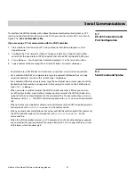
Table 6-1 lists the serial commands supported by the VHD Controller and the responses it 
sends back to the control system or PC. 

Table 6-1. Serial Commands and Responses 

Command

Description

Response

off

Turns projector off

Powering Down

on

Turns projector on

Powering Up


Gennum Init 


Complete

rev

Display system firmware version information:

> rev

* Vidikron Gennum Scaler Board *

* Rev 0.28 (T01) 05 Jan 2007 *

File Name:  Vidikron_Gennum.ncd

Created:    21 Dec 2006 - 10:42:40

Device:     XC3S100EVQ100

(see description)

Input Selection Commands

SSRC 0

Selects the Composite video input 

Composite

SSRC 1

Selects the S-Video input

S-Video

SSRC 2

Selects the Component RCA (HD1) input 

Component RCA

SSRC 3

Selects the Component BNC (HD2) input

Component BNC

SSRC 4

Selects the Component PC (HD3) input

Component PC

SSRC 5

Selects the RGB RCA (HD1) input 

RGB RCA

SSRC 6

Selects the RGB BNC (HD2) input

RGB BNC

SSRC 7

Selects the RGB PC (HD3) input

RGB PC

SSRC 8

Selects the HDMI 1 input

HDMI 1

SSRC 9

Selects the HDMI 2 input

HDMI 2

Aspect Ratio Commands

SAR 0

Selects the 16:9 aspect ratio

16:9

SAR 1

Selects the 4:3 aspect ratio

4:3

SAR 2

Selects the Letterbox aspect ratio

Letterbox

SAR 3

Selects the IntelliWide aspect ratio

IWide

SAR 4

Selects the Cinema aspect ratio

Cinema

SAR 5

Selects the IntelliWide 2.35 aspect ratio

IntelliWide 2.35

Содержание Vision 120

Страница 1: ...1080p Digital Light Processing DLP Projector Vision 120 Vision 120 CineWide Vision 120 CineWide with AutoScope 120 VERSION 1 1 O W N E R S O P E R A T I N G M A N U A L ...

Страница 2: ......

Страница 3: ...over normal maintenance This Limited Warranty does not cover cabinets or any appearance items failure resulting from accident misuse abuse neglect mishandling misapplication faulty or improper installation or setup adjustments improper maintenance alteration improper use of any input signal damage due to lightning or power line surges spikes and brownouts damage that occurs during shipping or tran...

Страница 4: ...epair These arrangements must be made through the selling Vidikron Dealer If this is not possible contact Vidikron directly for a Return Authorization number and shipping instructions Vidikron will return product transportation prepaid in the United States unless no product defect is discovered In that instance shipping costs will be the responsibility of the owner Copyright 2007 Vidikron a Runco ...

Страница 5: ..._ ________________________________________ Model Purchased Date ____________________________________________________________________________________________________________ Serial Number ____________________________________________________________________________________________________________ Vidikron Authorized Dealer Name ________________________________________________________________________...

Страница 6: ...he 12V trigger only outputs DC 12V signal for triggering Do not connect to any other power input or output This could cause damage to this unit 10 Only use accessories specified by Vidikron 11 Keep the packing material in case the equipment should ever need to be shipped 12 Unplug this projector during lightning storms or when it will not be used for an extended period of time 13 The lamp becomes ...

Страница 7: ... Rear Panel 6 VHD Controller Front Panel 8 VHD Controller Rear Panel 10 Vision 120 Remote Control 12 3 Installation 15 Remote Control 15 Notes on Batteries 15 Notes on Remote Control Operation 15 Quick Setup 16 Installation Considerations 17 Installation Type 17 Ambient Light 17 Throw Distance 18 Vertical and Horizontal Position 19 Vertical and Horizontal Lens Shift 19 Folded Optics 21 Other Consi...

Страница 8: ... IR Receiver to the VHD Controller 39 Connecting to AC Power 40 Turning on the Power 40 Adjusting the Picture Orientation 40 Primary Lens Adjustments 41 Focus 41 Zoom 41 Vertical and Horizontal Lens Shift 41 Installing and Adjusting the CineWide Anamorphic Lens 42 Attach Lens Mounting Assembly to Lens Motor Carriage Plate CineWide with AutoScope or Base Plate fixed CineWide 42 Configure Lens Motor...

Страница 9: ...er s Operating Manual ix P R E L I M I N A R Y 6 Serial Communications 67 RS 232 Connection and Port Configuration 67 Serial Command Syntax 67 7 Specifications 71 Vision 120 Specifications 71 VHD Controller Specifications 73 Vision 120 Dimensions 74 ...

Страница 10: ...Table of Contents x Vidikron Vision Model 120 Owner s Operating Manual P R E L I M I N A R Y Notes ...

Страница 11: ... Vision 120 to the VHD Controller 31 3 11 HDMI Source Connections 32 3 12 Digital DTV RGB or Component Video Connections HD1 HD2 33 3 13 Digital DTV RGB or Component Video Connections HD3 34 3 14 Analog RGB Connections 35 3 15 S Video and Composite Video Connections 36 3 16 RS 232 Control System Connection 37 3 17 12 volt Trigger Output Connections 38 3 18 External IR Receiver Connection 39 3 19 V...

Страница 12: ...List of Figures xii Vidikron Vision Model 120 Owner s Operating Manual P R E L I M I N A R Y Notes ...

Страница 13: ...l Vidikron welcomes your comments about this manual Send them to info Vidikron com Textual and Graphic Conventions Text Conventions The following conventions are used in this manual in order to clarify the information and instructions provided Remote and built in keypad button identifiers are set in upper case bold type for example Press EXIT to return to the previous menu Computer input commands ...

Страница 14: ...special significance They also provide supplemental information CAUTIONS alert users that a given action or omitted action can degrade performance or cause a malfunction WARNINGS appear when a given action or omitted action can result in damage to the equipment or possible non fatal injury to the user DANGER appears when a given action can cause severe injury or death Tip Note Caution WARNING DANG...

Страница 15: ...ital connections from input to light engine for absolutely stellar pictures In addition Vidikron s multiple aspect ratio control includes its unique IntelliWide mode for viewing standard video formats in widescreen without loss of image quality For uncompromising widescreen reproduction of movies originally filmed in the scope 2 35 1 format the Vision 120 can be equipped with Vidikron s patent pen...

Страница 16: ...ize batteries AC Power Cords for Projector and VHD Controller Rack mount hardware for the VHD Controller Warranty information and registration card Vidikron Vision Model 120 Owner s Operating Manual this document Optional Accessories Dual Link DVI Cable length specified at time of order available lengths range from 7 5 meters to 20 meters 24 6 feet to 65 6 feet CineWide technology fixed secondary ...

Страница 17: ...components Figure 2 1 Vision 120 Front Bottom Side View 1 PRIMARY PROJECTION LENS 2 VIDIKRON LOGO The logo can be rotated to match the projector orientation inverted ceiling mounted or upright To rotate the logo grip it at the sides pull it away from the projector and rotate it 180 degrees 3 EXHAUST VENTS 2 Controls and Functions 3 1 3 2 ...

Страница 18: ...ion 120 menu system 6 RIGHT BUTTON Used to move the menu cursor right in the Vision 120 menu system 7 STAND BY LED Lights orange to indicate that the projector is in standby mode 8 SOFT POWER BUTTON Press once to turn on the Vision 120 Press it again to put the projector into Standby mode For a discrete on or off command you can use the direct access buttons on the remote control see Figure 2 5 9 ...

Страница 19: ... High speed service port for future use 13 DVI DL Dual Link An HDCP compliant dual link digital video input for connecting the output from the VHD Controller 14 SELECT BUTTON Press SELECT to confirm your selection of a highlighted choice on the On Screen Display OSD 15 MENU BUTTON Pressing the MENU button brings up the main Vision 120 menu Also if you are in an adjustment mode or function pressing...

Страница 20: ...TTERN BUTTON Press PATTERN to access the internal test pattern menu Use arrow keys to select a pattern and press SELECT to confirm Press PATTERN again to return to the selected source 4 LEFT BUTTON Used to direct select inputs or move the menu cursor left in the OSD When no menu is present on screen the LEFT button toggles through the different sources in this order HDMI 2 HDMI 1 HD3 VGA Y Pb Pr H...

Страница 21: ...on one half second off for approximately 90 seconds after the system is turned off 9 ISSUE LED Lights red to indicate an error condition 10 UP BUTTON Use to direct select aspect ratios or move the menu cursor up in the OSD When no menu is present on screen the UP button toggles through aspect ratios in the following order 16 9 4 3 Letterbox IntelliWide Cinema IntelliWide 2 35 IntelliWide 2 35 is a...

Страница 22: ...ceiver It is a 3 5 mm mini phono jack wired as follows Ring 5V Tip IR Input TTL level Sleeve Ground 7 RS 232 485 CONTROL PORT A male 9 pin D sub connector for interfacing with a PC or home theater automation control system Currently only RS 232 interface is supported 8 12 VOLT 750 mA TRIGGER OUTPUTS Connection for up to three 3 12 volt trigger controlled devices These can be retractable screens sc...

Страница 23: ...t signal resolution 11 COMPOSITE VIDEO INPUT Standard composite video input for connecting a VCR laser disc player or other composite video source 12 S VIDEO INPUT A standard S Video input for connecting a DVD player satellite receiver or Super VHS S VHS VCR 13 HD2 INPUT Five BNCs for connecting either RGB or component high definition sources up to 1080p The VHD Controller automatically detects th...

Страница 24: ...ote control and the paragraphs that follow describe its functionality Figure 2 5 Vision 120 Remote Control FOCUS LENS ZOOM LIGHT OFF ON VID S VID HDMI1 HD2 SOURCE PICTURE MEMORY ASPECT RATIO HD1 INFO ENTER EXIT MENU BRT CUST1 CUST2 CONT COL TINT HD3 HDMI2 ISF DAY ISF NIGHT 16 9 IWIDE LBOX 4 3 CINEMA IWIDE 2 35 FOCUS ZOOM 2 1 5 4 6 3 9 8 0 7 LENS 1 4 2 3 5 7 6 8 9 ...

Страница 25: ...to display input signal and product information Cursor Keys Use these buttons to select items or settings adjust settings or switch display patterns EXIT Press to save menu item setting s exit the current menu and return to the previous one ENTER Press to select a highlighted menu item or confirm a changed setting This button functions similarly to the SELECT button on the projector rear panel Fig...

Страница 26: ... the screen LBOX Letterbox For viewing LaserDisc movies or non anamorphic DVDs on a 16 9 screen IWIDE IntelliWide Enlarges a 4 3 image horizontally in a NON linear fashion to fit 16 9 full screen display CINEMA For viewing 2 35 1 source material IWIDE 2 35 IntelliWide 2 35 CineWide equipped projectors only Selects the IntelliWide 2 35 aspect ratio used for viewing 16 9 source material on a 2 35 1 ...

Страница 27: ...ill not use the remote control for a long time remove the batteries to avoid damage from battery leakage Notes on Remote Control Operation Make sure that there is nothing obstructing the infrared beam between the remote control and the IR receiver on the projector If the effective range of the remote control decreases or it stops working replace the batteries with new ones The remote control may f...

Страница 28: ...nnect the VHD Controller to the projector 31 5 Connect signal sources to the VHD Controller 32 6 Connect external controller to RS 232 port optional 37 7 Connect 12 volt trigger outputs to AutoScope lens motor and or other equipment optional 38 8 Connect projector VHD Controller and lens motor if present to AC power and power up 40 9 For rear screen and or ceiling mount installations select the pr...

Страница 29: ...less vibrant Table 3 2 Projector Installation Options Advantages Considerations Front Screen Floor Mount Installation Easy to set up Can be moved or changed quickly Easy to access Shares floor space with audience Front Screen Inverted Mount ceiling Installation Does not take up audience space Projector is unobtrusive Projector cannot be accidentally moved Installation is more permanent Projector a...

Страница 30: ...e Table 3 3 lists the available lens options for the Vision 120 and their associated throw ratios Table 3 3 Vision 120 Lens Options and Throw Ratios Lens Option Note 2 Throw Ratio with Primary Lens Only Throw Range in inches with 96x54 inch 1 78 1 Screen Throw Ratio with Primary Lens and Anamorphic Lens Throw Range in inches with 126 9x54 inch 2 35 1 Screen Minimum Maximum Minimum Maximum A1 0 70 ...

Страница 31: ...e projector and screen as shown in Figure 3 2 you can use the lens shift controls to center the image on the screen Lens shift is generally expressed as a percentage of the screen height or width as shown in Figure 3 3 and Figure 3 4 Figure 3 3 Vertical Lens Shift EXAMPLE ONLY Height Projection Distance Ceiling Ceiling Installation Screen Height Floor Lens Center Projection Distance Floor Installa...

Страница 32: ...N A R Y Figure 3 4 Horizontal Lens Shift EXAMPLE ONLY 0 Screen Center 100 Width Lens Shift 1 0 x W 50 Width Lens Shift 0 5 x W Screen Width W Note This is a general example of lens shift Lenses vary in their shift capabilities No particular lens or projector is used in this example ...

Страница 33: ... Lens Option A1 A2 B C D E Lens Shift Limits as Percentages of Screen Height or Width Notes 1 and 2 Vertical Note 2 Up 10 31 30 32 28 30 Down 10 71 61 62 65 63 Horizontal Note 2 Left 5 17 12 Right 5 17 12 Lens Shift Limits in Inches with a 100 by 56 inch 1 78 1 Screen Vertical Up 5 60 17 36 16 80 17 92 15 68 16 80 Down 5 60 39 76 34 16 34 72 36 40 35 28 Horizontal Left 5 00 17 00 12 00 Right 5 00 ...

Страница 34: ...re may cause drifts in the projector circuitry which may affect performance Keep the projector away from devices that radiate electromagnetic energy such as motors and transformers Common sources of these include slide projectors speakers power amplifiers and elevators 3 4 Installing the Primary Projection Lens The projection lens is shipped separately from the projector To install it proceed as f...

Страница 35: ...he right side of the Lens Cavity Carefully insert the back of the lens assembly into the hole in the lens flange Gently push the lens assembly in until it is seated flush against the flange and the motor connectors have seated Make sure to route the wire harness in its original position and away from the moving lens stages and Motor Assembly to prevent unexpected disconnection or lens damage Cauti...

Страница 36: ... Projector Front Jewelry Tighten the hex screws at the top and bottom of the jewelry to secure it 3 5 Installing the Optional CineWide Lens Mount If you are installing a standard non CineWide Vision 120 skip this step and proceed with Mounting the Vision 120 page 30 If you are installing a Vision 120 CineWide proceed with Installing the Fixed CineWide Base Plate Vision 120 CineWide page 29 If you ...

Страница 37: ...1 Do not install the CineWide lens yet only the fixed CineWide base plate or AutoScope lens motor You will install the CineWide lens after you install the projector and adjust the primary lens 2 Some components shipped with your projector may differ slightly from what is shown in these instructions Note 3 4 Screw Phillips Pan Head M6 1 0 x 12mm 14x 1 AutoScope Lens Motor 2 CineWide with AutoScope ...

Страница 38: ... adapters bring the attachment points for the projector mounting rails included with the projector ceiling mount kit from the bottom of the projector up and around the AutoScope lens motor housing For floor installations where the projector is upright the adapters allow the projector to lie flat on the mounting surface Using six 6 each of the supplied M6 x 12mm Pan Head Phillips screws item 2 atta...

Страница 39: ...Installation Vidikron Vision Model 120 Owner s Operating Manual 27 P R E L I M I N A R Y Figure 3 7 Vision 120 with Ceiling Mount Adapters Projector Stands DO NOT OVER TIGHTEN THE SCREWS Caution ...

Страница 40: ...wn in Figure 3 8 Line up the mounting holes on the lens motor housing with those on the underside of the projector Secure the motor to the projector with the eight 8 remaining M6 x 12mm Pan Head Phillips screws item 2 Figure 3 8 AutoScope Lens Motor Installation After you have installed the AutoScope lens motor proceed with Mounting the Vision 120 page 30 ...

Страница 41: ...de 1 Place the projector upside down on a blanket or other soft surface 2 Line up the mounting holes on the lens mount base plate with those on the bottom of the projector directly below the primary lens see Figure 3 9 3 Secure the base plate to the projector with the screws provided for this purpose Figure 3 9 Installing the Fixed CineWide Base Plate CineWide Base Plate Screw Phillips Pan Head M6...

Страница 42: ... can invert the Vision 120 and suspend it from the ceiling using a specially designed ceiling mount fixture The projector can also be inverted and placed in an enclosure above and behind the viewing area Install four feet on the inside bottom surface of the enclosure on which the projector can rest A variety of materials can be used for this purpose for example rubber crutch tips or turntable feet...

Страница 43: ...y digital input signals directly from the companion VHD Controller Processor All signal sources should be connected to the appropriate inputs on the rear panel of the controller The signal from the controller is then output to the Vision 120 projector through a DVI DL dual link cable Use a Vidikron DVI Dual Link DVI DL cable to connect the output of the VHD Controller to the input of the Vision 12...

Страница 44: ...t follow HDMI Connections See Figure 3 11 Figure 3 11 HDMI Source Connections Use the HDMI inputs whenever possible This ensures the highest video quality because the signal is carried in the digital domain throughout the entire signal path from source component output into the projector Tip HD3 VGA Y Pb Pr COMPOSITE S VIDEO HD2 BNC Vs Hs Pr R Pb B Y G Vs HDMI II I HDMI Source HD DVD BD DVD Player...

Страница 45: ...3 12 and Figure 3 13 Figure 3 12 Digital DTV RGB or Component Video Connections HD1 HD2 II I III TRIGGERS 32 485 HD3 VGA Y Pb Pr COMPOSITE S VIDEO HD2 BNC Vs Hs Pr R Pb B Y G HD1 RCA Y G Vs Hs Pr R Pb B HDMI II I Green Y Blue Pb Red Pr Horiz Vert G Y B Pb R Pr H V DTV or Progressive Component YPbPr Source DTV or Progressive Component YPbPr Source ...

Страница 46: ... s Operating Manual P R E L I M I N A R Y Figure 3 13 Digital DTV RGB or Component Video Connections HD3 HD3 VGA Y Pb Pr COMPOSITE S VIDEO HD2 BNC Vs Hs Pr R Pb B Y G DMI II Green Y Blue Pb Red Pr Horiz Vert DTV or Progressive Component YPbPr Source ...

Страница 47: ... Operating Manual 35 P R E L I M I N A R Y Analog Computer RGB Connections See Figure 3 14 Figure 3 14 Analog RGB Connections HD3 VGA Y Pb Pr COMPOSITE S VIDEO HD2 BNC Vs Hs Pr R Pb B Y G HDMI II Green Y Blue Pb Red Pr Horiz Vert Personal Computer ...

Страница 48: ...ing Manual P R E L I M I N A R Y S Video Composite Video Connections See Figure 3 15 Figure 3 15 S Video and Composite Video Connections HD3 VGA Y Pb Pr COMPOSITE S VIDEO HD2 BNC Vs Hs Pr R Pb B Y G HDMI II I DVD Player VCR Satellite Receiver Laser Disc etc ...

Страница 49: ...485 port on the VHD Controller see Figure 3 16 For more information about using this connection refer to Serial Communications on page 67 Figure 3 16 RS 232 Control System Connection II I TRIGG RS 232 485 WIRED REMOTE SERVICE ONLY SYSTEM CONTROL INTERFACE HD1 Y G Pr R Pb B INPUTS Service port Not for user access 1 2 3 4 5 7 8 9 6 to Automation Control System or PC 5 Ground 3 Transmit Data 2 Receiv...

Страница 50: ... Similarly connect other 12 volt trigger activated equipment such as retractable screens or screen masks to the other trigger outputs For more information on using the VHD Controller triggers refer to Triggers on page 62 Figure 3 17 12 volt Trigger Output Connections II I III TRIGGERS RS 232 485 ERFACE Y HD1 RCA Y G Vs Hs Pr R Pb B HDMI I I INPUTS DHD Controller Rear Panel AutoScope Lens Motor Rea...

Страница 51: ... 18 External IR Receiver Connection When an external IR receiver is connected to the wired IR input the built in IR sensor on the VHD Controller is disabled II I TRIGGERS RS 232 485 WIRED REMOTE SERVICE ONLY SYSTEM CONTROL INTERFACE HD1 RC Y G Pr R Pb B INPUTS Service port Not for user access VHD Controller Rear Panel Ring 5V Tip IR Input Sleeve Ground 3 5 mm mini phono plug IR Receiver Remote Con...

Страница 52: ... PWR button on the VHD Controller front panel to turn on the system The vacuum fluorescent display on the VHD Controller front panel briefly displays Starting Display 5 When the projector is ready for use after about 20 seconds the RUN LED on the VHD Controller front panel lights solid blue The fluorescent display indicates the current input source aspect ratio and input resolution for example 3 9...

Страница 53: ... image use the cursor buttons to highlight In or Out Then press and hold the ENTER button on the remote control Zoom To make the picture smaller zoom out use the cursor buttons to highlight the minus sign Then press and hold the ENTER button on the remote control To enlarge the picture zoom in use the cursor buttons to highlight the plus sign Then press and hold the ENTER button on the remote cont...

Страница 54: ...ting Assembly Exploded View 1 Remove the two Yaw X Adjustment Levers item 8 from the bottom of the Anamorphic Lens Holder item 5 2 Place the Anamorphic Lens Holder on top of the AutoScope Carriage Plate or fixed CineWide Base Plate item 7 Position the bracket so that the long slot at the bottom of the lens holder is perpendicular to the corresponding slots on the plate It is extremely important th...

Страница 55: ...the Pitch Adjustment Yoke item 2 see Figure 3 20 Use the round threaded holes on the yoke 5 Use the Height Y Adjustment T Screws item 3 Pitch Adjustment T Screws item 4 and T Nuts item 9 to attach the Pitch Adjustment Yoke and Lens Adapter Ring to the Anamorphic Lens Holder The Yoke should be as close to the primary lens as possible 6 Attach the lens to the Lens Adapter Ring by threading it clockw...

Страница 56: ...he Service menu 5 Assign the trigger output to which the lens motor is connected to the Cinema and IntelliWide 2 35 aspect ratios This enables the lens motor to move the anamorphic lens into position in front of the primary lens when either aspect ratio is selected 6 To save the trigger settings press repeatedly to highlight Save Then press ENTER 7 Select the Cinema aspect ratio to move the anamor...

Страница 57: ...h Adjustment T Screws directly below the Height Y Adjustment T Screws on either side of the lens to allow it to pivot freely Then adjust the anamorphic lens angle so that the projected image is rectangular The anamorphic lens will almost always be angled with respect to the projector this is normal Once the proper lens angle has been set firmly tighten the Pitch Adjustment T Screws to secure the l...

Страница 58: ...the Yaw X Adjustment Levers to allow the lens to pivot freely from side to side Then angle the lens to even out any left right pincushion distortion Once the proper lens angle has been set firmly tighten the Yaw X Adjustment Levers to secure the lens in place Anamorphic Lens Top View Wrong Position Correct Position ...

Страница 59: ...y 3 Grasp the lens by the center ring and rotate the lens until the image is properly anamorphic 4 When the image geometry appears correct tighten the Anamorphic Lens Set Screw item 10 to secure the lens in place When viewed from the front the rear opening on the anamorphic lens should appear as a tall narrow oval Focus Finally rotate the Focus Ring on the anamorphic lens to fine tune the optical ...

Страница 60: ...Installation 48 Vidikron Vision Model 120 Owner s Operating Manual P R E L I M I N A R Y Notes ...

Страница 61: ... 2 To select a menu item use the and buttons on the remote control VHD Controller front panel or projector rear panel to highlight it Then to confirm your selection press ENTER on the remote control or SELECT on the VHD Controller front panel or projector rear panel The Vision 120 OSD menus are arranged hierarchically as shown in Figure 4 1 Depending on the selected input source and signal charact...

Страница 62: ...NC HD2 RGB PC HD3 HDMI 1 HDMI 2 Aspect Ratio 16 9 4 3 Letterbox IntelliWide Cinema IntelliWide 2 35 Picture Brightness Contrast Color Tint Sharpness Input Position Left Right Up Down Width Height Overscan Phase RGB Component signals only ISF Presets Recall ISF Night Recall ISF Day Recall Save Custom 1 Recall Save Custom 2 Reset Custom 1 2 to Factory Default Information read only Resolution Firmwar...

Страница 63: ... the projected image select Aspect Ratio from the Main Menu and press ENTER or SELECT Select the appropriate aspect ratio for your screen size and the type of program material being viewed refer to Table 4 1 The currently selected aspect ratio is indicated by a 7 to its left in this example 16 9 is selected Vision Model 120 Input Source Aspect Ratio Picture Input Position ISF Presets Information C...

Страница 64: ...ttes Letterbox LBOX Letterbox mode scales zooms in on a 4 3 image linearly by the same amount on all sides to fill a 16 9 display Letterbox is best suited for viewing LaserDisc movies or non anamorphic DVDs on a 16 9 screen IntelliWide IWIDE IntelliWide scales a 4 3 image NON linearly more on the sides than in the center to fit a 16 9 screen On a 2 35 1 screen the image is centered between black b...

Страница 65: ...rtions of the screen are masked but the geometry of the active image area is unchanged With a 2 35 1 screen and a CineWide equipped projector the VHD Controller scales the 2 35 1 image so that the active image area fills the 16 9 chip surface eliminating the black bars The secondary anamorphic lens then restores the proper geometry to the 2 35 1 image IntelliWide 2 35 IWIDE 2 35 A 16 9 image is sc...

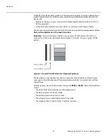
Страница 66: ... listed here Brightness On your external test pattern source select a PLUGE pattern PLUGE is an acronym for Picture Line Up Generation Equipment Figure 4 2 shows a typical PLUGE pattern Figure 4 2 Typical PLUGE Pattern for Adjusting Brightness PLUGE patterns vary but generally consist of some combination of black white and gray areas against a black background The example above includes two vertic...

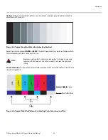
Страница 67: ...ER or SELECT Adjust the contrast to a point just below which the white rectangle starts to increase in size Color Saturation On your external test pattern source select a color bar pattern like the one shown in Figure 4 4 Figure 4 4 Typical Color Bar Pattern for Adjusting Color Saturation and Tint Brightness and contrast controls are interactive A change to one may require a subtle change to the o...

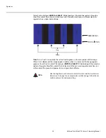
Страница 68: ...n of the image When tint is decreased the image appears redder when it is increased the image appears greener To set the tint select Tint and press ENTER or SELECT While looking at the color bar pattern through a blue filter adjust the tint level until the cyan and magenta color bars on either side of the green bar appear to be a single shade of blue Like the brightness and contrast controls the c...

Страница 69: ...nput Position Menu to fine tune the aspect ratio and image position for the current source Left Right Select Left Right from the Input Position menu to shift the projected image horizontally Press to shift the image to the right press to shift it to the left Up Down Select Up Down from the Input Position menu to shift the projected image vertically Press to shift the image upward press to shift it...

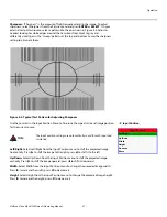
Страница 70: ...n one point Use either setting in this case ISF Presets For each input the Vision 120 lets you save image quality settings as presets that you can recall at a later time You can create up to four presets per input and resolution Use the ISF Presets menu to recall saved image presets or to save image settings in the Custom 1 or Custom 2 memory location The currently selected preset is indicated by ...

Страница 71: ... black and maximum input white for all signals A good gamma setting helps to optimize blacks and whites while ensuring smooth transitions for the in between values utilized in other grays Unlike Brightness and Contrast controls the overall tone of your images can be lightened or darkened without changing the extremes and all images will be more vibrant while still showing good detail in dark areas...

Страница 72: ...gh frequencies may also soften the image ISF Day Display Color Refer to ISF Night Display Color ISF Day Input Image Refer to ISF Night Input Image ISF Day Input Color Refer to ISF Night Input Color Save ISF Settings Whenever you make a change to the ISF settings you should always save it Select Save ISF Settings from the ISF Calibration menu to do this In the event you ever have to perform a Syste...

Страница 73: ...then select Red Green Blue Yellow Cyan or Magenta to display only that color simulating a filter of that color This can be useful for calibration or measurement purposes To restore the normal picture all colors select White HD Format Select HD Format from the Service menu to choose the default color space for the source signals on the HD1 HD2 and HD3 inputs Select COMP component or RGB The VHD Con...

Страница 74: ...hroma Upsampling Error Correction Some DVD players use MPEG decoders that do not correctly upsample the 4 2 0 format chroma information on the DVD to the 4 2 2 or 4 4 4 format required by the video encoder of the display device This so called chroma bug sometimes causes streaky or spiky horizontal lines running through the chroma channel It is most noticeable in static interlaced scenes and on dia...

Страница 75: ...nt 2 Loosen and remove the rear Lamp Cover screw 3 Slide the Lamp Cover in the direction of the arrow to remove it 4 Loosen the two captive lamp assembly mounting screws using a coin or a large flat blade screwdriver 5 Grasp the lamp assembly handle and pull gently removing the lamp module from the projector housing 5Maintenance and Troubleshooting The Vision 120 lamp is under high pressure Handle...

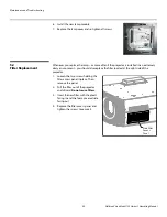
Страница 76: ...ctor is installed in an extremely dusty environment you should also replace the filter located at the right side of the projector 1 Loosen the two screws holding the filter access panel in place Then remove the panel 2 Pull the filter out of the projector and discard Do not reuse filters 3 Insert the new filter with the pleats facing in and the foam covered side facing out 4 Replace the filter acc...

Страница 77: ...ection Source component is not turned on Select the correct source Turn on the source A projected image from a DVD is split or otherwise scrambled DVD player is set to progressive scan mode Turn off progressive scan on the DVD player Image is too bright and or lacks definition in the bright areas of the image Contrast is set too high Lower the contrast setting Image appears washed out and or dark ...

Страница 78: ...Maintenance and Troubleshooting 66 Vidikron Vision Model 120 Owner s Operating Manual P R E L I M I N A R Y Notes ...

Страница 79: ...s type the command followed by a carriage return for example to turn on the system type ON Enter For a command that takes a parameter type the command one or more spaces and the desired value followed by a carriage return for example to switch to the S Video input type SSRC 1 Enter When you enter a valid command the VHD Controller executes it When you send an on off input selection aspect ratio or...

Страница 80: ...lection Commands SSRC 0 Selects the Composite video input Composite SSRC 1 Selects the S Video input S Video SSRC 2 Selects the Component RCA HD1 input Component RCA SSRC 3 Selects the Component BNC HD2 input Component BNC SSRC 4 Selects the Component PC HD3 input Component PC SSRC 5 Selects the RGB RCA HD1 input RGB RCA SSRC 6 Selects the RGB BNC HD2 input RGB BNC SSRC 7 Selects the RGB PC HD3 in...

Страница 81: ...mmands These commands provide active OSD responses just like the IR remote ENTR ENTER or SELECT button none EXIT EXIT button MENU MENU button MND Down Arrow button MNL Left Arrow button MNR Right Arrow button MNU Up Arrow button Picture Adjust Commands The following serial commands are meant to emulate the discrete picture adjustment buttons on the remote control unit Use them in conjunction with ...

Страница 82: ...Serial Communications 70 Vidikron Vision Model 120 Owner s Operating Manual P R E L I M I N A R Y Notes ...

Страница 83: ...ct Ratios Refer to Table 7 2 Video Standards Refer to Table 7 2 DTV Compatibility 480i 576i 480p 576p 1080i 50 60 720p 50 60 1080p 24 50 60 1080psf Scan Frequency Horizontal 15 100 kHz Vertical 28 78 Hz Picture Size 16 9 Screen Recommended Width 72 120 in Maximum Width 250 in Throw Distance Factor x Screen Width Refer to Table 3 3 Horizontal and Vertical Offset Refer to Table 3 4 Lamp 300W UHP Est...

Страница 84: ...t is dependent on screen size screen gain and projector light output Home Theater Calibration Specifications Light Output 1380 ANSI Lumens Contrast Ratio 320 1 These specifications are obtained by calibrating the projector as described above for CSMS measurements Industry Standard Specifications Light Output 2825 ANSI Lumens Contrast Ratio 4000 1 These are typical projector brightness and contrast...

Страница 85: ...l Link with HDCP Control Options Discrete infrared remote Serial commands via RS 232 interface Front panel controls RS 232 Communication Parameters 19200 bps no parity 8 data bits 1 stop bit no flow control Trigger Outputs 3 12 VDC each rated at 750 mA and thermal fuse protected Bandwidth 150 Mega Samples per Second MSPS Power Requirements 100 to 240 VAC auto sensing 50 60 Hz 160 Watts Operating E...

Страница 86: ...Vision 120 dimensions all dimensions are in inches Figure 7 1 Vision 120 CineWide with AutoScope Dimensions 0 2 47 6 44 17 69 18 65 23 60 12 18 7 60 16 76 4 89 0 1 65 8 43 8 96 0 5 36 6 01 1 21 9 09 7 39 19 55 30 29 0 1 65 4 00 14 73 12 44 23 55 30 29 9 00 0 7 01 11 72 15 97 20 22 29 66 29 08 22 90 23 97 10 74 30 41 35 41 36 32 32 49 3 00 ...

Страница 87: ......

Страница 88: ...Vidikron 2900 Faber Street Union City CA 94587 510 324 5900 Fax 510 324 5905 1 888 4 VIDIKRON www vidikron com SERIAL NUMBER RUMA 011255 rev 11 13 07 v1 1 ...

Отзывы: