background image

EXPLANATION OF CRITICAL GROOVE DIMENSIONS FOR  

ORIGINAL GROOVE SYSTEM (OGS) PRODUCTS

 WARNING

•  Pipe dimensions and groove dimensions must be within the tolerances specified in the 

tables on the following pages to ensure proper joint performance.

Failure to follow these specifications could cause joint failure, resulting in serious personal 
injury and/or property damage.
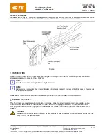
A

B

D

B

T

C

OD

F

Standard Roll Groove

Exaggerated for clarity

Pipe Outside Diameter – 

The average pipe outside diameter must not vary from the specifications 

listed in the tables on the following pages . Maximum allowable pipe ovality should not vary by more 
than 1% . Greater variations between the major and minor diameters will result in difficult coupling 
assembly .

The maximum allowable tolerance from square-cut pipe ends is: 


1/32

 inch/0 .8 mm for 2 – 3 1/2-inch/60 .3 – 101 .6-mm sizes and 

1/16

 inch/1 .6 mm for 

4-inch/114 .3-mm and larger sizes . This is measured from the true square line .

"S" Max.

Raised internal and external weld beads and seams must be ground flush with the pipe surface  
2 inches/50 mm back from the pipe ends . The inside diameter of the pipe end must be cleaned to 
remove coarse scale, dirt, and other foreign material that might interfere with or damage grooving 
rolls . The front edge of the pipe end shall be uniform with no concave/convex surface features that 
will cause improper grooving roll tracking and result in difficulties during coupling assembly .

“A” Dimension –

 The “A” dimension, or the distance from the pipe end to the groove, identifies the 

gasket seating area . This area must be free from indentations, projections (including weld seams), 
and roll marks from the pipe end to the groove to ensure a leak-tight seal . All foreign material, such 
as loose paint, scale, oil, grease, chips, rust, and dirt must be removed .

“B” Dimension –

 The “B” dimension, or groove width, controls expansion, contraction, and angular 

deflection of flexible couplings by the distance it is located from the pipe and its width in relation to 
the coupling housings’ “key” width . The bottom of the groove must be free of all foreign material, 
such as dirt, chips, rust, and scale that may interfere with proper coupling assembly . 

“C” Dimension –

 The “C” dimension is the average diameter at the base of the groove . This 

dimension must be within the diameter’s tolerance and concentric with the OD for proper coupling 
fit . The groove must be of uniform depth for the entire pipe circumference .

26

REV_C

TM-RG3212 

/ Operating and Maintenance Instructions Manual

Содержание OGS RG3212

Страница 1: ...tructions in this manual and all warning labels on the tool Wear safety glasses hardhat foot protection and hearing protection while working around this tool Save this operating and maintenance manual...

Страница 2: ......

Страница 3: ...ring Pipe for Grooving 10 Short Pipe Lengths 10 Long Pipe Lengths 11 Groove Diameter Stop Adjustment 12 Grooving Operation 14 Lower Roll Removal 16 Upper Roll Removal 17 Upper Roll Installation 18 Low...

Страница 4: ...es listed in the Tool Ratings section These instructions must be read and understood by each operator PRIOR to working with the grooving tools These instructions describe safe operation of the tool in...

Страница 5: ...ain proper footing and balance at all times CAUTION 1 This tool is designed ONLY for roll grooving pipe sizes materials and wall thicknesses listed in the Tool Ratings section 2 Inspect the equipment...

Страница 6: ...Tool Ratings for Steel Pipe section of this manual Use of the tool for other purposes or use exceeding the pipe thickness maximums will overload the tool shortening tool life and potentially causing...

Страница 7: ...are not available and an extension cord must be used it is important to use the proper cord size gauge Cord size selection is based upon tool rating and cord length Use of a cord size gauge thinner t...

Страница 8: ...nd Hydraulic Pump Handle Lower Roll Lower Roll Nut Power Cord Power Switch Hydraulic Cylinder Locking Nut Depth Adjuster Nut Hydraulic Pump Valve Upper Roll Foot Switch 8 REV_C TM RG3212 Operating and...

Страница 9: ...er Requirements section b The space necessary to adequately handle the pipe to be grooved c A level surface for the tool and pipe stand 3 Place the tool on a level surface Place a level on top of the...

Страница 10: ...the pipe end must be cleaned to remove coarse scale dirt and other foreign material that might interfere with or damage grooving rolls The front edge of the pipe end shall be uniform with no concave c...

Страница 11: ...eve the required angle of pipe Place Pipe Stand Slightly Beyond Half the Pipe Length from theTool Tool Centerline Level Pipe Centerline Level to 1 Below Level for 2 8 inch Pipe Sizes 0 50 to 1 00 Belo...

Страница 12: ...oper material diameter and wall thickness Refer to Tables 1 and 2 for the minimum pipe lengths required for grooving Hand Pump Valve 2 Insert a piece of pipe of the correct size and wall thickness ont...

Страница 13: ...oove completion 9 After a trial groove is prepared and the pipe is removed from the tool carefully check the C groove diameter Refer to the Roll Groove Specifications section The C groove diameter dim...

Страница 14: ...that all instructions in the previous sections of this manual have been followed 2 Plug the RG3212 into an internally grounded electrical source 3 Turn the switch on the side of the tool to the ON po...

Страница 15: ...itioned properly 11 With the switch in the ON position the pipe will begin to rotate clockwise As the pipe rotates begin grooving by using the hydraulic pump handle NOTICE Do not pump the hydraulic pu...

Страница 16: ...aft can cause fragmentation resulting in serious personal injury 2 To remove the lower roll from the arbor loosen the lower roll retaining nut until it reaches the end of the lower shaft Do not fully...

Страница 17: ...g the knob counterclockwise This will raise the slide and upper roll to their highest positions 2 Loosen the upper shaft retaining screw It is not necessary to completely remove the screw 3 While supp...

Страница 18: ...ng screw to retain the upper roll on the upper shaft 4 Lubricate upper roll bearing with a No 2EP lithium based grease Refer to the Maintenance section for additional information LOWER ROLL INSTALLATI...

Страница 19: ...or with a spray type heavy duty open gear lubricant HYDRAULIC SYSTEM The level of hydraulic fluid should be checked before operation and must be checked several times per year especially if the hydrau...

Страница 20: ...universal ball unit Work the light machine oil in by rotating the universal ball units PARTS ORDERING INFORMATION When ordering parts the following information is required for Victaulic to process the...

Страница 21: ...ing on long pipe Pipe is overtracking Refer to the Long Pipe Lengths section Pipe end is not cut square Cut pipe end squarely Pipe is rubbing excessively hard on the lower roll Remove pipe from tool a...

Страница 22: ...2 5 2 3 3 500 0 083 0 216 0 216 0 216 88 9 2 1 5 5 5 5 5 5 31 2 4 000 0 083 0 226 0 226 0 226 101 6 2 1 5 7 5 7 5 7 4 4 500 0 083 0 237 0 237 0 237 Roll Set R904321206 114 3 2 1 6 0 6 0 6 0 5 5 563 0...

Страница 23: ...2 1 3 0 4 4 500 0 083 0 120 Roll Set RX04321206 114 3 2 1 3 0 5 5 563 0 109 0 134 141 3 2 8 3 4 6 6 625 0 109 0 134 168 3 2 8 3 4 8 8 625 0 109 0 148 Roll Set RX08321212 219 1 2 8 3 8 10 10 750 0 134...

Страница 24: ...237 127 0 2 4 6 0 5 5 563 0 109 0 258 0 258 0 375 141 3 2 8 6 6 6 6 9 5 152 4mm 6 000 0 109 0 258 152 4 2 8 6 6 6 6 625 0 109 0 280 0 280 0 432 168 3 2 8 7 1 7 1 11 0 8 8 625 0 109 0 322 0 322 0 322 R...

Страница 25: ...083 Roll Set RR02321206 54 0 1 1 2 1 2 1 2 2 625 0 065 0 095 66 7 1 7 2 4 3 3 125 0 045 0 109 79 4 1 1 2 8 4 4 125 0 058 0 134 104 8 1 5 3 4 5 5 125 0 072 0 160 130 2 1 8 4 1 6 6 125 0 083 0 192 155...

Страница 26: ...remove coarse scale dirt and other foreign material that might interfere with or damage grooving rolls The front edge of the pipe end shall be uniform with no concave convex surface features that will...

Страница 27: ...ured at the extreme pipe end diameter NOTE This applies to average pi tape and single point readings T Dimension The T dimension is the lightest grade minimum nominal wall thickness of pipe that is su...

Страница 28: ...5 8 0 97 4 96 9 2 2 2 0 104 1 108 0 mm 4 250 4 293 4 219 0 625 0 656 0 594 0 344 0 375 0 313 4 084 4 064 0 083 0 078 4 35 108 0 109 0 107 2 15 9 16 7 15 1 8 7 9 5 8 0 103 7 103 2 2 2 2 0 110 5 4 4 50...

Страница 29: ...215 5 19 1 19 8 18 3 11 9 12 7 11 1 211 6 211 0 2 4 2 8 220 7 8 8 625 8 688 8 594 0 750 0 781 0 719 0 469 0 500 0 438 8 441 8 416 0 092 0 109 8 80 200 219 1 220 7 218 3 19 1 19 8 18 3 11 9 12 7 11 1 2...

Страница 30: ...53 DWV 4 220 104 8 104 8 104 7 15 5 16 3 14 7 8 4 7 6 102 1 101 6 1 4 107 2 5 5 127 5 123 0 610 0 640 0 580 0 330 0 300 4 999 4 979 0 063 DWV 5 220 130 2 130 2 130 1 15 5 16 3 14 7 8 4 7 6 127 0 126 5...

Страница 31: ...This page intentionally blank 31 REV_C TM RG3212 Operating and Maintenance Instructions Manual...

Страница 32: ...IS A REGISTERED TRADEMARK OF VICTAULIC COMPANY AND OR ITS AFFILIATED ENTITIES IN THE UNITED STATES AND OR OTHER COUNTRIES 2021 VICTAULIC COMPANY ALL RIGHTS RESERVED OPERATING AND MAINTENANCE INSTRUCT...

Отзывы: